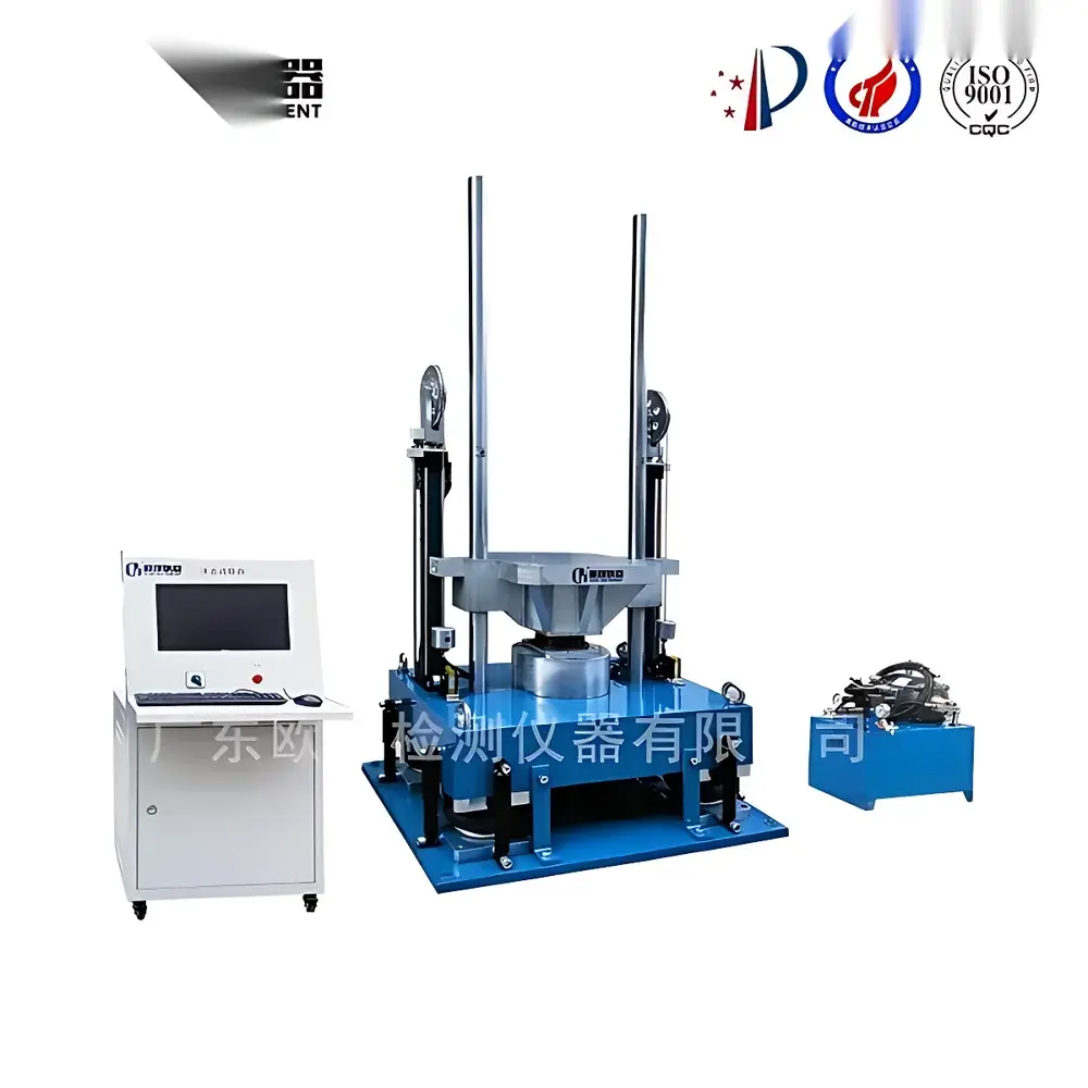
Other Brands AC-2000 Vertical Mechanical Shock Test System
| Brand | Other Brands |
|---|---|
| Origin | Imported |
| Manufacturer Type | Authorized Distributor |
| Max Load Capacity | 10 kg |
| Shock Table Dimensions | 200 × 200 mm |
| Pulse Duration Range | 0.2–100 ms (programmable, auto-controlled) |
| Peak Acceleration Range | 50–9999 m/s² (programmable, auto-controlled) |
| Standard Pulse Shape | Half-sine |
| Shock Direction | Vertical |
| Secondary Impact Prevention | Hydraulic-friction braking system |
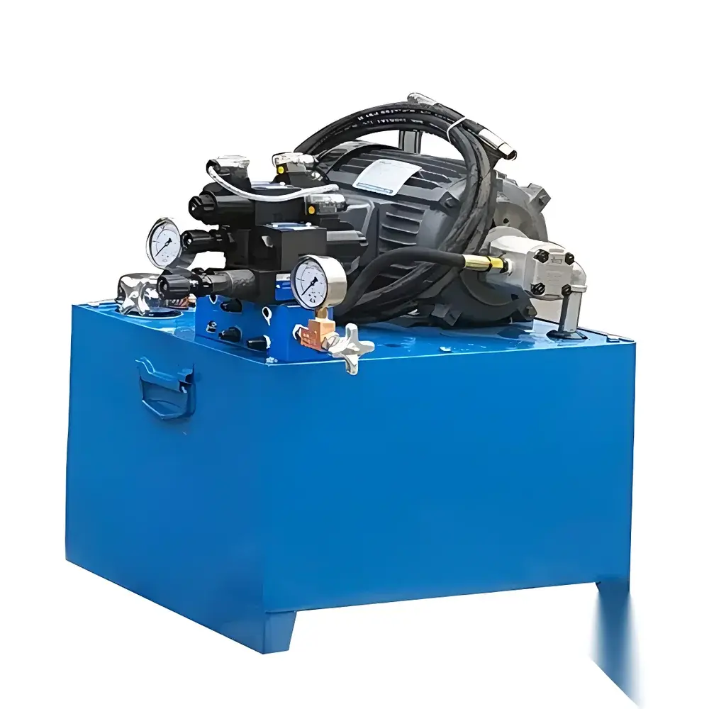
| Height Control | Digital preset + hydraulic lifting |
| Power Supply | AC 380 V ±10%, 50 Hz, 3 kVA |
| System Weight | 2800 kg |
| Overall Dimensions | 750 × 2600 × 1000 mm |
| Repetition Rate | 0–100 shocks/min (programmable, ±1% accuracy) |
| Sampling Rate | 200 kHz |
| Signal Conditioning | Analog anti-aliasing filters + 160 dB/octave digital anti-aliasing filter |
| Compliance Standards | IEC 60068-2-27, GB/T 2423.5, GJB 150.18A, GJB 360B, JJG 497 |
| Data Engine | DAO-based Windows XP platform |
| Report Generation | Automated Word report export |
| Real-time Display | Lift height, peak acceleration, pulse width, Δv, system status |
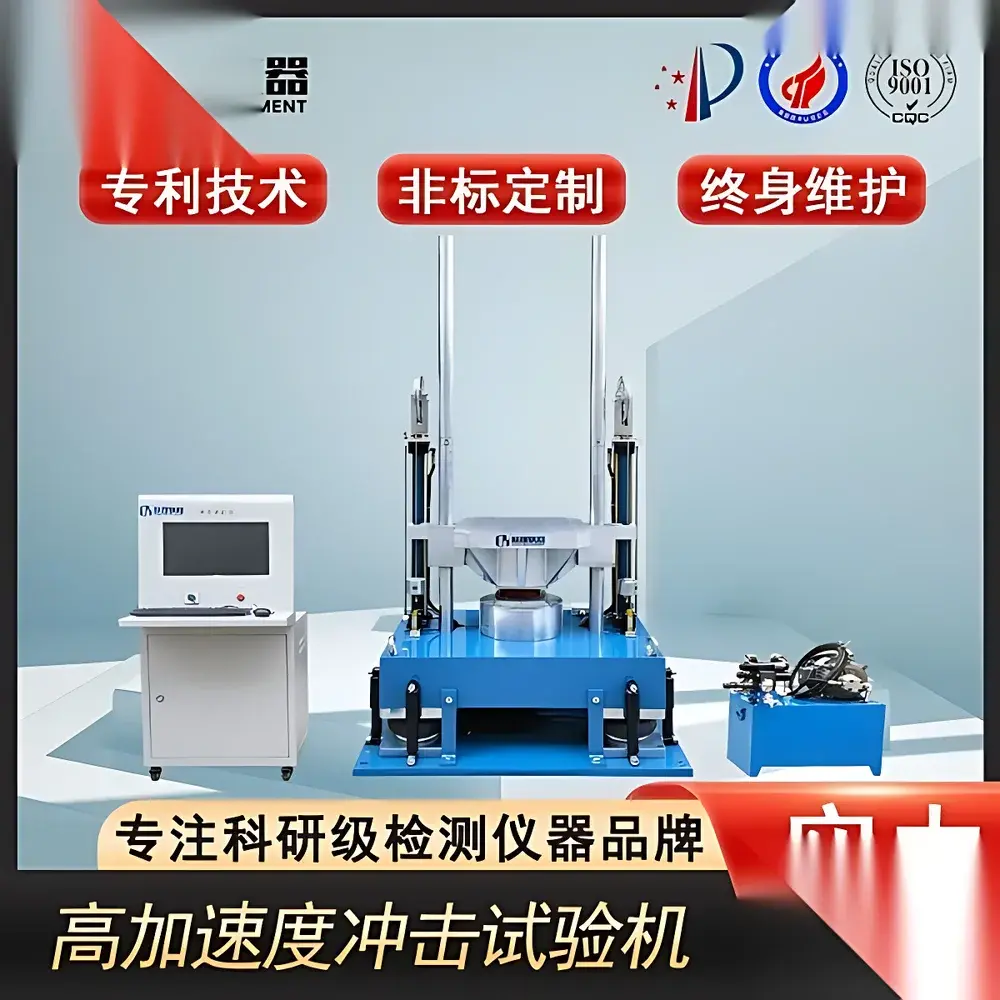
Overview
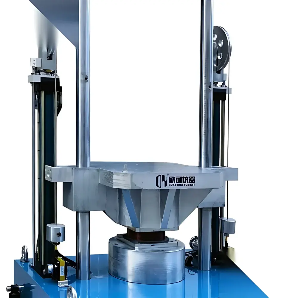
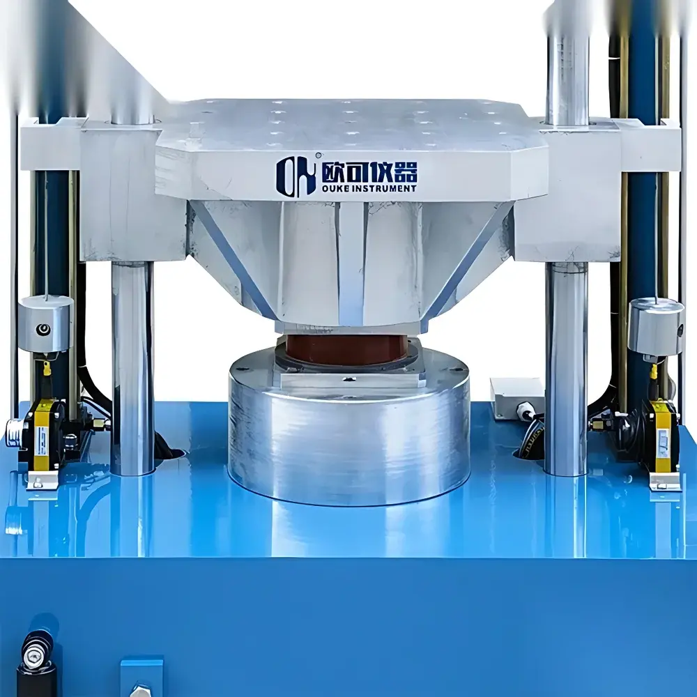
The AC-2000 Vertical Mechanical Shock Test System is a precision-engineered shock simulation platform designed for laboratory and industrial qualification testing of electronic components, aerospace subsystems, automotive modules, and packaged goods. It operates on the principle of controlled free-fall impact generation, where a test specimen mounted on a rigid shock table is accelerated vertically via hydraulic lifting and released to impact a calibrated elastomeric or metallic stopper—producing a repeatable half-sine acceleration pulse. The system is engineered for high reproducibility in transient mechanical stress application, enabling compliance verification against internationally recognized environmental stress screening (ESS) and qualification test standards including IEC 60068-2-27, GB/T 2423.5, and MIL-STD-810H Method 516.6 (Shock). Its robust architecture supports deterministic shock pulse generation with precise control over pulse duration, peak acceleration magnitude, and waveform fidelity—critical parameters for evaluating structural integrity, solder joint reliability, and functional survival under sudden inertial loading.
Key Features
- Programmable half-sine shock pulse generation with user-defined peak acceleration (50–9999 m/s²) and pulse duration (0.2–100 ms), both adjustable via digital interface with ±1% measurement accuracy.
- Hydraulic lifting mechanism with digital height presetting ensures consistent drop height and eliminates manual calibration drift across repeated test cycles.
- Dual-stage signal conditioning: analog anti-aliasing filtering combined with a 160 dB/octave digital anti-aliasing filter enables clean acquisition at 200 kHz sampling rate—preserving transient fidelity without spectral leakage.
- Integrated hydraulic-friction braking system prevents secondary rebound impact, eliminating post-pulse oscillations that compromise test validity and specimen safety.
- Real-time monitoring interface displays lift height, instantaneous acceleration amplitude, measured pulse width, velocity change (Δv), and system operational status—all synchronized with data acquisition.
- Self-calibrating pulse alignment algorithm automatically tracks and adjusts for allowable waveform tolerance zones per IEC/GB/GJB specifications (e.g., front 0.4D–rear 0.1D; front 0.4D–rear 1.1D), ensuring conformance without manual waveform trimming.
Sample Compatibility & Compliance
The AC-2000 accommodates specimens up to 10 kg mass on its 200 × 200 mm rigid aluminum shock table. Mounting fixtures (not included) must comply with ISO 10816-3 vibration mounting guidelines to minimize boundary condition artifacts. The system meets full metrological traceability requirements for shock testing laboratories operating under GLP or ISO/IEC 17025 accreditation frameworks. It satisfies waveform tolerance criteria defined in IEC 60068-2-27 (Figure 2: Half-sine pulse tolerances), GB/T 2423.5 (Clause 6.2), GJB 150.18A (Section 4.3.2), and JJG 497 (National Verification Regulation for Shock Test Systems). All shock parameters—including pulse symmetry, zero-baseline stability, and rise/fall time consistency—are verified during factory calibration using NIST-traceable piezoelectric accelerometers and dynamic charge amplifiers.
Software & Data Management
The embedded control and analysis software operates natively on Windows XP Embedded (SP3) with DAO-based data persistence architecture. It supports real-time acquisition, time-domain waveform visualization, FFT-based spectral validation, and statistical post-processing (min/max/mean/SD across multi-cycle runs). All raw time-series data are stored in binary .BIN format with embedded metadata (test ID, operator, timestamp, calibration certificate ID). The software generates fully editable Microsoft Word reports compliant with internal QA templates and external audit requirements—including automatic inclusion of waveform plots, parameter tables, pass/fail flags per standard clause, and digital signature fields for GLP/GMP 21 CFR Part 11 readiness (when deployed with validated Windows domain authentication and audit log configuration). Export options include CSV, PDF, and XML for LIMS integration.
Applications
- Qualification testing of avionics enclosures per DO-160 Section 8 (Shock).
- Solder joint fatigue assessment in PCB assemblies subjected to transport-induced shock events.
- Drop-test correlation studies for consumer electronics packaging design validation.
- Functional survivability evaluation of MEMS sensors, optical modules, and battery management systems under high-g transient loads.
- Calibration and verification of onboard shock data recorders used in flight test instrumentation.
- Environmental stress screening (ESS) protocols for high-reliability defense electronics per MIL-STD-883 Method 2006.
FAQ
What standards does the AC-2000 support out-of-the-box?
The system is pre-configured for IEC 60068-2-27, GB/T 2423.5, GJB 150.18A, GJB 360B, and JJG 497, with built-in waveform tolerance masks and automated pass/fail evaluation.
Is the software compatible with modern Windows OS versions?
The native control software requires Windows XP Embedded; however, data export (CSV, Word, PDF) is fully interoperable with Windows 10/11 for offline analysis and reporting.
Can the system perform sequential shock profiles (e.g., multiple pulses with varying amplitudes)?
Yes—the test sequence editor supports up to 99 programmable shock steps with independent settings for acceleration, duration, interval, and repetition count.
What maintenance is required for long-term waveform accuracy?
Annual recalibration of the accelerometer channel and mechanical drop-height verification are recommended; hydraulic fluid and brake pad inspection should occur every 12 months or after 5,000 shocks, whichever comes first.
Does the system include shock response spectrum (SRS) calculation capability?
SRS generation is available as an optional software module compliant with MIL-STD-810H Annex G and ECSS-Q-ST-70-02C methodologies.
Related Products


