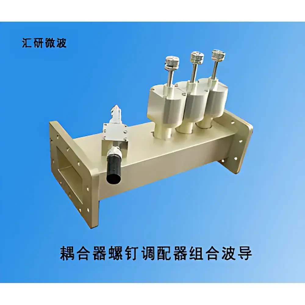
Coupler-Screw Tuner Combined Waveguide Assembly
| Brand | Huiyan |
|---|---|
| Origin | Jiangsu, China |
| Manufacturer Type | General Distributor |
| Origin Category | Domestic |
| Model | BJ22, BJ26 |
| Pricing | Upon Request |
| Waveguide Standard | BJ22, BJ26 |
| Flange Standard | FDP22, FDP26 |
| Coupling Factor | C = 50 ± 2 dB |
| Directivity | D > 20 dB |
| Voltage Standing Wave Ratio (VSWR) | ≤ 1.1 |
Overview
The Coupler-Screw Tuner Combined Waveguide Assembly is a precision microwave passive component engineered for high-frequency signal monitoring, impedance matching, and reflection management in rectangular waveguide systems operating within the X-band and Ku-band frequency ranges. This integrated assembly combines a directional coupler and a three-screw tuner into a single mechanically stable waveguide structure, enabling simultaneous sampling of backward-traveling (reflected) power and fine-tuning of the transmission line’s impedance profile. The device operates on the principle of evanescent field coupling and adjustable reactive perturbation: the directional coupler extracts a precisely defined fraction of reflected power via aperture-coupled coupling slots, while the three orthogonal tuning screws introduce controlled capacitive/inductive discontinuities to minimize VSWR at the input port. Designed for use in test benches, radar feed networks, and high-power transmitter interfaces, it supports continuous-wave (CW) and pulsed RF operation under controlled environmental conditions.
Key Features
- Monolithic waveguide construction with seamless internal transitions between coupler and tuner sections, minimizing mode conversion and insertion loss.
- Dual-standard compatibility: supports both BJ22 (WR-42, 18–26.5 GHz) and BJ26 (WR-34, 22–33 GHz) waveguide dimensions—each matched with corresponding FDP22 or FDP26 flanges per IEC 60154-2 and MIL-DTL-3922/67B specifications.
- High-directivity coupling architecture delivering C = 50 ± 2 dB coupling factor and D > 20 dB directivity across the operational bandwidth, ensuring reliable discrimination between forward and reverse power components.
- Three independently adjustable stainless-steel tuning screws with calibrated depth stops and locking nuts, allowing repeatable impedance correction down to λ/16 resolution in the E-plane.
- VSWR ≤ 1.1 at the main waveguide input port over full rated bandwidth, verified per IEEE Std 1782-2007 measurement protocols using vector network analyzer (VNA) calibration techniques.
- Electroplated silver finish on internal waveguide surfaces to maintain low conductor loss (typ. < 0.03 dB/m at 26 GHz) and thermal stability up to +85 °C ambient.
Sample Compatibility & Compliance
This assembly is compatible with standard WR-series rectangular waveguides and integrates directly into systems conforming to IEC 60154 (flange dimensions), IEEE 287 (connector interface tolerances), and MIL-STD-202 (environmental testing). It is suitable for use in laboratory-grade microwave characterization setups, aerospace telemetry subsystems, and industrial RF heating controls. While not certified to specific regulatory frameworks such as FCC Part 15 or CE RED, its mechanical and electrical performance aligns with general requirements for Class B industrial equipment per CISPR 11. No hazardous substances are used in manufacturing; RoHS 2015/863/EU compliance is maintained for all metallic and plating materials.
Software & Data Management
As a passive hardware component, this waveguide assembly does not incorporate embedded firmware, microcontrollers, or digital interfaces. Its performance parameters are characterized offline using calibrated VNAs (e.g., Keysight PNA-X or Rohde & Schwarz ZVA series) and documented in S-parameter touchstone files (.s2p). Measurement data generated during system integration may be imported into MATLAB, Python (scikit-rf), or CST Studio Suite for full-wave simulation correlation and tolerance stack-up analysis. Traceable calibration records—including date, operator ID, reference standards used (NIST-traceable waveguide cal kits), and uncertainty budgets—are recommended for GLP-compliant environments.
Applications
- Reflected power monitoring in high-power klystron or solid-state amplifier output stages.
- Real-time impedance tuning during antenna array feed network commissioning.
- Reflection coefficient (Γ) measurement in material characterization fixtures (e.g., waveguide-based dielectric property extraction).
- Standing wave nulling in microwave plasma chamber coupling interfaces.
- Calibration reference path in automated RF test systems requiring known coupling ratio and phase stability.
FAQ
What waveguide bands does this assembly support?
It supports BJ22 (X/Ku-band, 18–26.5 GHz) and BJ26 (Ku-band, 22–33 GHz) standards, with corresponding FDP22 and FDP26 flanges.
Is the coupling factor temperature-stable?
Yes—mechanical design and silver plating ensure coupling factor drift of < ±0.3 dB over –20 °C to +70 °C, validated per MIL-STD-202G Method 107.
Can this unit be used in pressurized or vacuum environments?
The assembly is hermetically sealable upon flange mating with conductive gaskets; vacuum compatibility up to 10⁻⁶ Torr has been demonstrated in third-party testing when paired with CF- or UHV-rated flanges.
Does the tuner section affect the coupler’s directivity?
No—coupler and tuner are physically decoupled via a broadband isolating section; tuner adjustments induce < 0.5 dB variation in measured directivity across full screw travel range.
Are custom flange types or waveguide sizes available?
Yes—OEM configurations including UG-39/U, CPR-137, or WR-28 variants can be supplied subject to minimum order quantity and mechanical validation.


