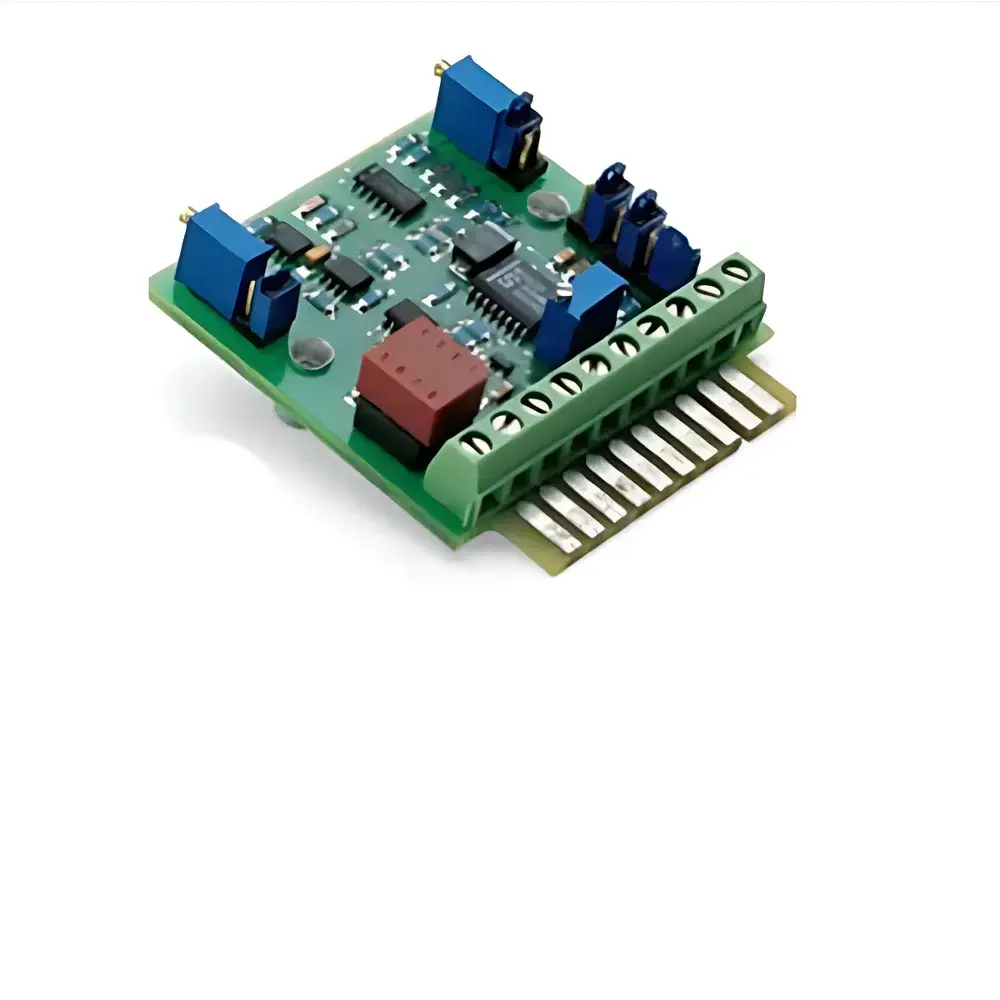
Firstmark LVM-110 Series LVDT Signal Conditioning Voltage Module
| Brand | Firstmark |
|---|---|
| Origin | Germany |
| Manufacturer Type | Authorized Distributor |
| Product Origin | Imported |
| Model | LVM-110 Series |
| Excitation Frequency Options | 2.5 kHz / 5 kHz / 10 kHz (jumper-selectable) |
| Output Types | 0–10 VDC unipolar (100% zero suppression), ±10 VDC bipolar (gain-selectable via 6-position jumper) |
| Input Compatibility | 5-wire and 6-wire LVDTs |
| LVDT Input Range | 100 mVrms to 5.6 Vrms full-scale |
| Zero Adjustment | 20-turn onboard potentiometer (±2 V, ±20% range) |
| Scale Adjustment | Onboard multi-turn span potentiometer per gain setting |
| Synchronization | Master/slave jumper option for multi-module synchronization |
| Mounting | Edge-mounted PC card format (extended PCB edge connector), also supports DIN rail or chassis mounting per OEM request |
| Power Supply | DC only |
Overview
The Firstmark LVM-110 Series LVDT Signal Conditioning Voltage Module is an engineered analog signal processor designed specifically for high-stability, low-noise conditioning of Linear Variable Differential Transformer (LVDT) outputs in precision industrial metrology, aerospace test benches, and automated quality control systems. Based on classic carrier-based synchronous demodulation architecture, the module converts the AC differential voltage output of LVDT sensors into stable, calibrated DC voltage signals—enabling direct integration with PLCs, data acquisition systems, and motion controllers without external signal processing hardware. Its core circuitry comprises a precision oscillator, AC-coupled amplifier, phase-sensitive demodulator, active low-pass filtering, and regulated DC output stage—all implemented using industrial-grade components selected for thermal stability and long-term repeatability. The LVM-110 operates exclusively from a DC power source, eliminating reliance on external AC excitation supplies and reducing electromagnetic interference susceptibility in electrically noisy environments.
Key Features
- Three selectable excitation frequencies (2.5 kHz, 5 kHz, or 10 kHz) via DIP-style jumpers—optimized for LVDT coil inductance and core material characteristics
- Configurable output modes: unipolar 0–10 VDC with 100% zero suppression across full LVDT stroke, or bipolar ±10 VDC with six discrete gain settings matching LVDT sensitivity ranges (100 mVrms to 5.6 Vrms)
- Dual-stage zero adjustment: fine-tuning via 20-turn onboard potentiometer (±2 V range), plus coarse offset selection via two-position jumper (±4 V fixed step), enabling precise null alignment even under mechanical preload or thermal drift conditions
- Span calibration per gain setting using dedicated multi-turn potentiometer—ensuring linearity compliance over full sensor range regardless of selected output scale
- Master/slave synchronization capability via jumper—eliminates beat frequency artifacts and cross-talk when multiple LVM-110 modules condition parallel LVDT channels in synchronized measurement arrays
- Robust mechanical design featuring extended-edge PCB mount compatible with standard 100 mm or 160 mm Eurocard slots; optional DIN rail or custom chassis mounting available for OEM integration
Sample Compatibility & Compliance
The LVM-110 is compatible with industry-standard 5-wire and 6-wire LVDT transducers—including both shielded and unshielded configurations—supporting common core materials (e.g., nickel-iron alloys, stainless steel) and typical stroke lengths from ±0.25 mm to ±250 mm. It meets IEC 61000-6-2 (immunity) and IEC 61000-6-4 (emission) requirements for industrial environments. While not certified to specific functional safety standards (e.g., IEC 61508), its analog signal path architecture ensures deterministic behavior suitable for SIL-1 applications when integrated into validated system-level architectures. All calibration and configuration procedures align with ISO/IEC 17025 traceability principles when performed using NIST-traceable reference standards.
Software & Data Management
As a purely analog signal conditioner, the LVM-110 does not incorporate embedded firmware, USB interfaces, or digital communication protocols. Its configuration is fully hardware-defined via physical jumpers and potentiometers—ensuring immunity to software corruption, cyber intrusion, or firmware version conflicts. This architecture supports long-term validation integrity in regulated environments governed by FDA 21 CFR Part 11 and EU Annex 11, where audit trails for hardware-configured measurement chains are maintained through documented calibration records and jumper configuration logs—not electronic change controls. For systems requiring digital archiving, the conditioned DC output may be digitized via compliant DAQ hardware meeting GLP/GMP data integrity requirements.
Applications
- Precision displacement monitoring in hydraulic actuator feedback loops for flight control surface testing
- Thermal expansion compensation in semiconductor wafer handling stages
- Dynamic strain measurement in structural health monitoring of wind turbine blades
- Calibration traceability transfer in national metrology institute primary standards labs
- OEM integration into coordinate measuring machine (CMM) probe electronics and laser interferometer auxiliary axes
- High-reliability position feedback for nuclear fuel rod inspection rigs operating under EMI-intensive conditions
FAQ
What LVDT excitation frequencies does the LVM-110 support, and how are they selected?
The module supports 2.5 kHz, 5 kHz, and 10 kHz excitation frequencies, selected via three-position jumper blocks located near the oscillator section.
Can the LVM-110 interface with both 5-wire and 6-wire LVDTs?
Yes—it is explicitly designed for compatibility with both topologies, including center-tapped and fully differential winding configurations.
Is there factory calibration documentation included?
Each unit ships with a Certificate of Conformance; NIST-traceable calibration certificates are available as an optional add-on service.
Does the module support hot-swap or redundant power input?
No—it requires a single, stabilized DC supply (specification provided in OEM integration manual); redundancy must be implemented at the system level.
How is synchronization achieved across multiple LVM-110 modules?
Via master/slave jumper configuration, which aligns internal oscillator phases to prevent inter-channel beat frequencies during simultaneous multi-axis measurements.