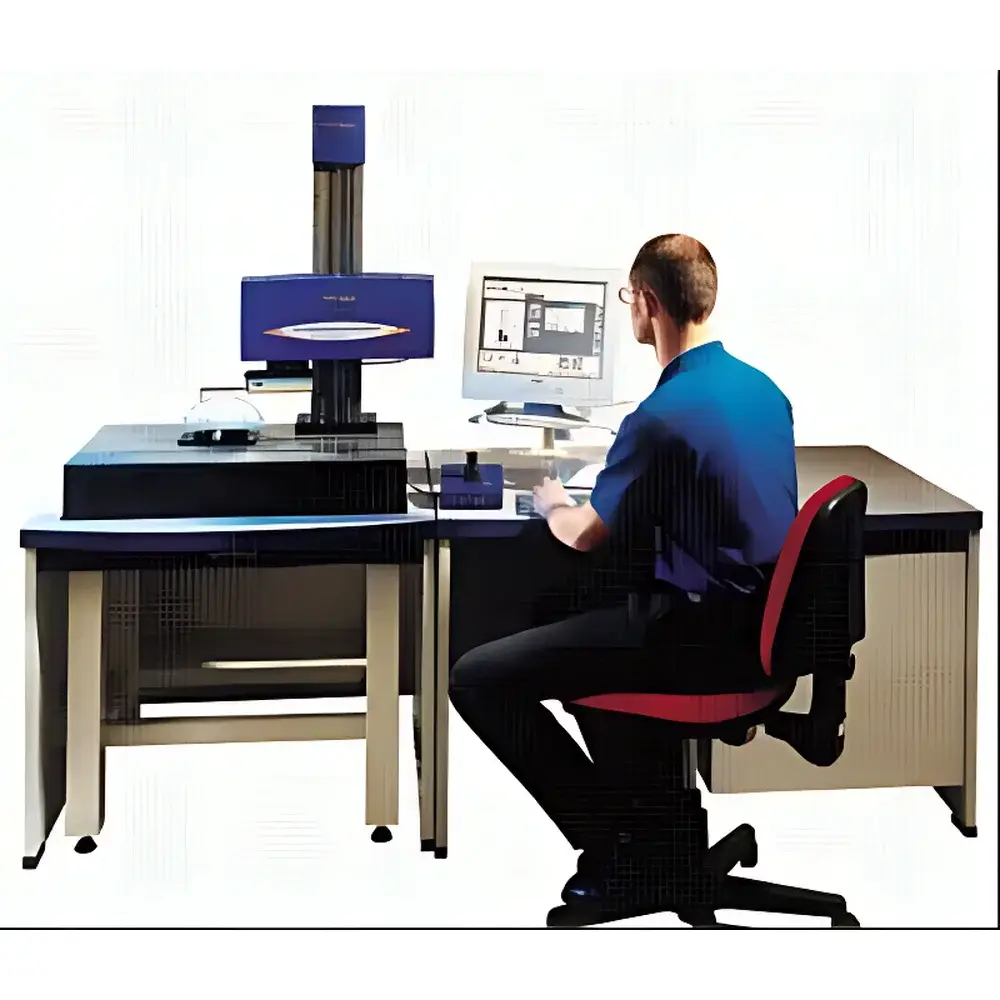
Form Talysurf Inductive Profilometer
| Origin | UK |
|---|---|
| Manufacturer Type | Authorized Distributor |
| Origin Category | Imported |
| Model | Form Talysurf Inductive |
| Price Range | USD 27,000 – 41,000 (est.) |
| Product Type | Contact Profilometer / Surface Roughness Tester |
| Measurement Length | 0.1 mm – 120 mm |
| Drive Method | Joystick or Computer-Controlled Motorized Traverse |
| Vertical Resolution | Up to 0.6 nm |
| Traverse Options | 50 mm / 120 mm / 200 mm Carriages |
| Measurement Modes | 2D Profile, 3D Areal Topography |
| Automation | Fully Programmable Auto-Operation for Batch Testing |
| Software | Multi-Option Analysis Suite with ISO 4287/4288, ISO 25178, ASME B46.1, and EN ISO 11562 Compliance |
Overview
The Form Talysurf Inductive Profilometer is a high-precision, modular contact-based surface metrology system engineered for traceable, repeatable characterization of surface topography and roughness in industrial quality control and advanced research laboratories. Built upon the proven inductive transducer principle—where a diamond-tipped stylus traverses the surface while an electromagnetic sensor detects minute vertical displacements—the instrument delivers sub-nanometer vertical resolution (down to 0.6 nm) and exceptional linearity over extended measurement ranges. Its rigid granite base, low-noise air-bearing carriage design, and thermally stable mechanical architecture ensure metrological integrity across temperature fluctuations and extended operational cycles. Designed and manufactured in the UK, the system conforms to international metrological best practices and serves as a primary reference tool for calibration labs, aerospace component suppliers, medical device manufacturers, and precision optics facilities requiring compliance with ISO/IEC 17025-accredited measurement protocols.
Key Features
- Modular platform supporting interchangeable configurations: dedicated roughness gauge, contour profiler, or combined roughness-and-contour instrument—enabling single-system adaptability across diverse inspection workflows.
- Three standard traverse carriage options (50 mm, 120 mm, and 200 mm) accommodate micro-feature analysis, macro-profile evaluation, and full-part form verification without hardware reconfiguration.
- Programmable auto-operation with script-driven measurement sequences—including automatic lift/drop, speed ramping, multi-pass acquisition, and conditional logic—optimized for unattended batch testing in production environments.
- Dual-mode operation: supports both 2D profile analysis (per ISO 4287/4288) and 3D areal topography mapping (per ISO 25178-2), with synchronized lateral and vertical data capture at up to 10,000 points/mm² density.
- Integrated vibration isolation and active thermal drift compensation ensure long-term stability during multi-hour measurements—critical for high-magnification form error assessment (e.g., roundness, flatness, waviness).
Sample Compatibility & Compliance
The Form Talysurf Inductive accommodates a broad range of engineering materials—including hardened steels, sapphire substrates, silicon wafers, polymer films, and additive-manufactured metal parts—without requiring conductive coating or vacuum conditions. Its 2 µm radius diamond stylus (standard) and optional 0.5 µm or 12.5 µm tips enable optimized contact pressure selection per ISO 11562 Annex B guidelines. All measurement algorithms adhere strictly to ISO 4287 (roughness parameters), ISO 13565 (material ratio curves), ISO 25178-2 (areal parameters), and ASME B46.1 standards. The system supports GLP/GMP audit trails, electronic signatures, and 21 CFR Part 11-compliant software modules when configured with certified firmware and validated installation qualification (IQ/OQ/PQ) documentation.
Software & Data Management
The instrument operates with Talymaster 7 software—a Windows-based metrology suite featuring real-time visualization, parameter mapping, statistical process control (SPC) dashboards, and customizable reporting templates. Raw data is stored in vendor-neutral .xyz and .csv formats; metadata includes full traceability of calibration certificates, environmental logs (temperature/humidity), operator ID, and instrument configuration history. Advanced modules support filtering (Gaussian, robust Gaussian), segmentation (peak-valley identification), functional characterization (Rk family, volume parameters), and GD&T overlay (e.g., tolerance zone comparison against CAD models). Data export complies with ASTM E2918 and ISO 14253-1 requirements for uncertainty reporting.
Applications
- Aerospace: Blade root profile verification, turbine disk waviness assessment, and seal land roughness validation per Rolls-Royce RRES 90060 or GE Aerospace PSS-1000 specifications.
- Medical Devices: Surface texture analysis of orthopedic implants (ISO 14644-1 cleanliness correlation), stent strut finish evaluation, and dental CAD/CAM crown margin integrity testing.
- Semiconductors: Wafer edge profile metrology, MEMS structure height uniformity, and CMP endpoint detection via sequential roughness trending.
- Automotive: Cylinder bore cross-hatch angle quantification, gear flank waviness mapping, and injection mold cavity replication fidelity assessment.
- Academic Research: Tribological interface modeling, thin-film adhesion correlation studies, and nanoscale wear track morphology reconstruction.
FAQ
What stylus tip radius options are available, and how do they affect measurement validity?
Standard tip radius is 2 µm (ISO 11562-compliant for most machined surfaces); optional 0.5 µm tips enable high-resolution micro-roughness capture on polished optics, while 12.5 µm tips improve durability on abrasive ceramics.
Can the system perform traceable calibration without external artifacts?
Yes—the integrated reference step-height standard (certified to ±0.5 nm uncertainty) enables in-situ calibration verification per ISO 5436-1; NIST-traceable calibration kits are available for full accreditation.
Is 3D areal measurement supported natively, or does it require additional hardware?
3D mapping is fully native using the motorized X-Y scanning stage (optional on 120/200 mm carriages); no add-on modules or external scanners are required.
How is measurement uncertainty reported in compliance with ISO/IEC 17025?
Talymaster 7 generates GUM-compliant uncertainty budgets incorporating repeatability, stylus geometry error, thermal expansion coefficients, and environmental monitoring inputs—exportable as PDF or XML.
Does the system support integration with MES or PLM platforms?
Yes—via OPC UA and RESTful API interfaces, enabling direct data push to Siemens Opcenter, PTC Windchill, or custom SPC databases with configurable field mapping and authentication protocols.