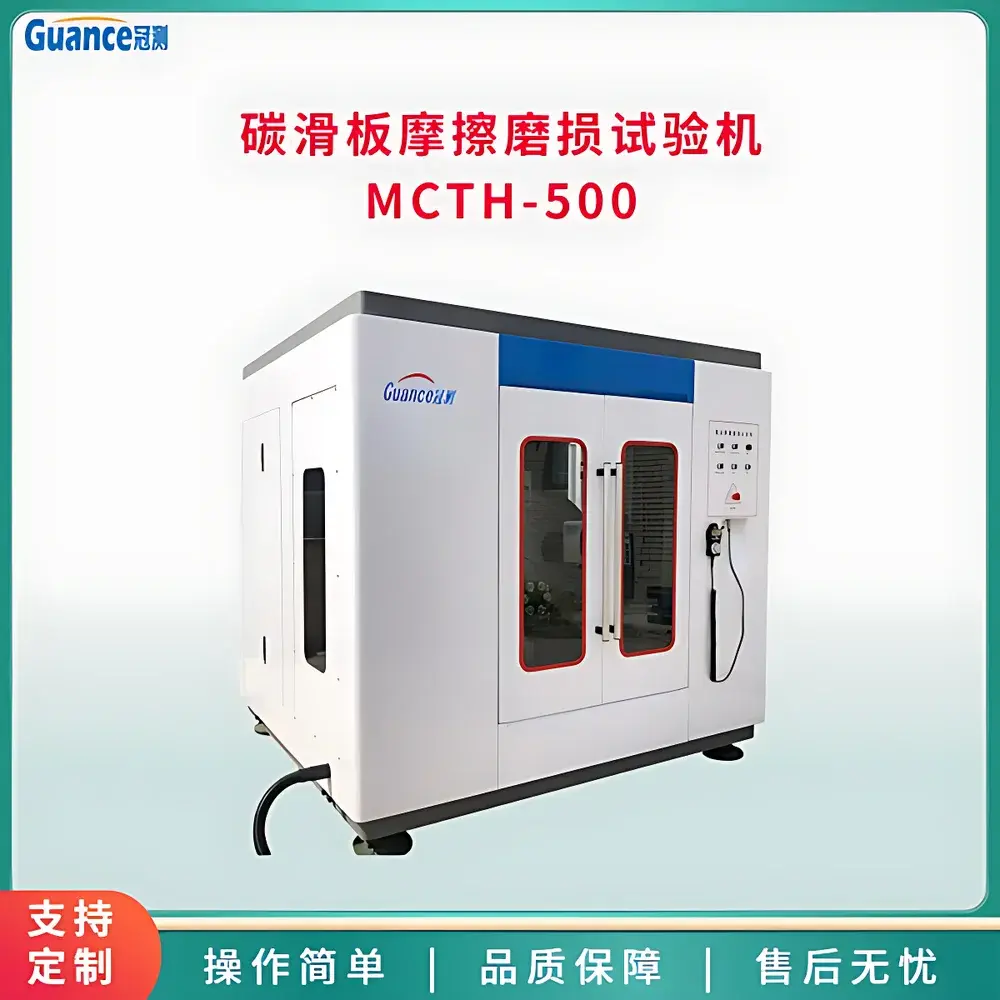
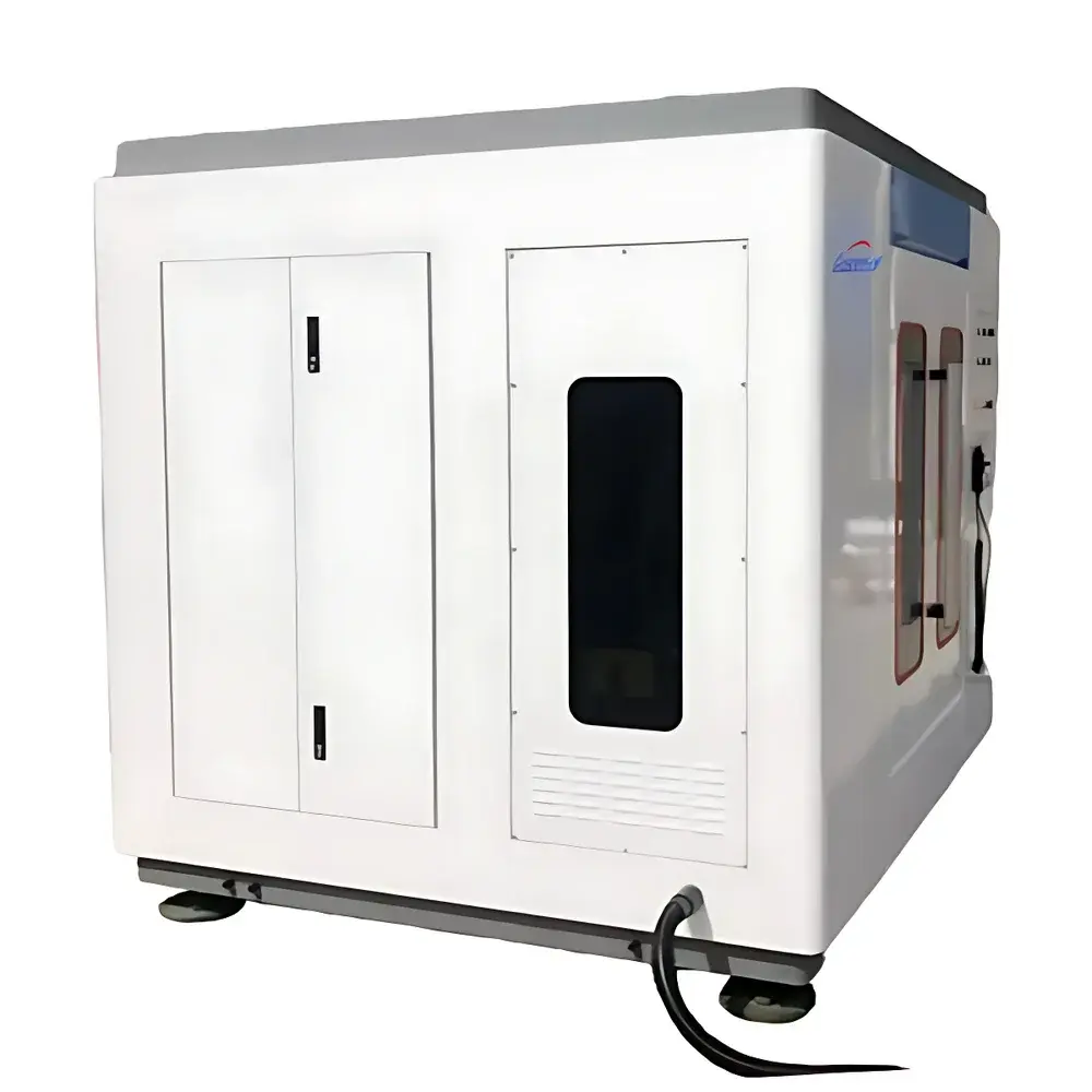
Guance MCTH-500 Fully Automated Carbon Pantograph Sliding Wear Tester
| Brand | Guance Instruments |
|---|---|
| Origin | Beijing, China |
| Model | MCTH-500 |
| Maximum Friction Force Range | 30–150 N (via calibrated deadweight loading) |
| Operating Ambient Temperature | −30 to +40 °C |
| Relative Humidity | ≤85 % RH |
| Atmospheric Pressure | 80–120 kPa |
| Supply Voltage | 220 ±10 % VAC, 50 ±0.5 Hz |
| Total Power Consumption | 20 kW |
| Rotating Disc Diameter | 420 mm |
| Disc Rotational Speed | 2600 rpm |
| Vertical Stroke of Carbon Slider | 100 mm |
| Stroke Frequency | 90 cycles/min |
| Electrical Test Input | 5 V / 500 A AC (adjustable via servo-controlled variac and high-current generator, 3 kVA capacity) |
| Radial Runout Measurement | Integrated dial indicator (0–360° indexed turntable) |
| Data Acquisition | Real-time voltage, current, and rotational speed logging with Excel export |
| Dust Extraction | 3 kW industrial vacuum system |
| Dimensions (L×W×H) | 1500 × 1000 × 1700 mm |
| Weight | 600 kg |
Overview
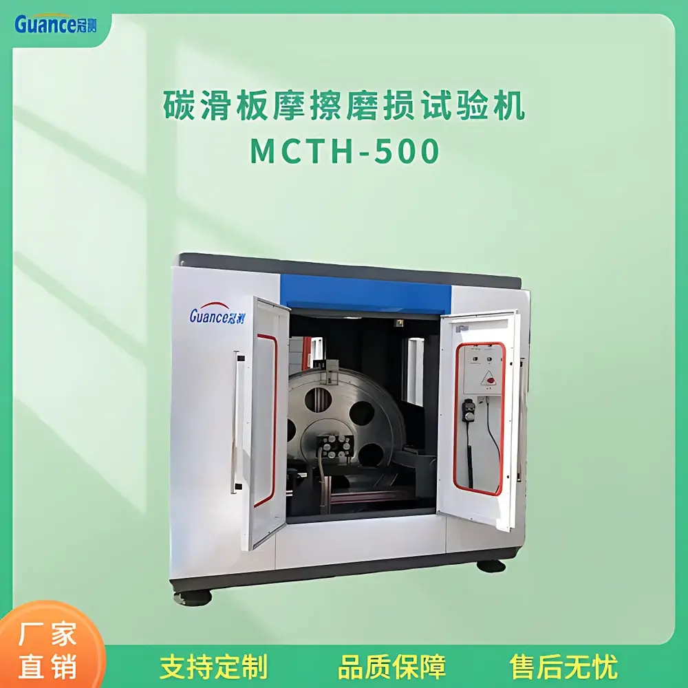
The Guance MCTH-500 Fully Automated Carbon Pantograph Sliding Wear Tester is an electromechanically integrated tribological testing platform engineered for standardized evaluation of carbon-based current-collecting materials—specifically pantograph carbon sliders—under dynamic, electrified sliding conditions. It replicates the operational interface between a stationary overhead contact wire and a vertically oscillating carbon slider under controlled normal load, electrical current, and relative velocity. The system employs a rotating disc (420 mm diameter, up to 2600 rpm) to simulate the effective linear velocity of a moving catenary system (equivalent to ~200 km/h), while the carbon slider executes programmable vertical reciprocation (100 mm stroke, 90 cycles/min) to emulate pantograph bounce and dynamic contact force variation. Frictional energy dissipation, electrical resistance evolution, and mass loss are monitored concurrently during test execution, enabling quantitative assessment of wear rate, arc erosion resistance, and contact stability per IEC 62196-3, EN 50317, and GB/T 25304–2010 requirements for railway current collection components.
Key Features
- Electrified tribological simulation: Delivers precisely regulated AC current (0–500 A at 5 V) via a servo-motor-driven variac and dedicated 3 kVA high-current generator, ensuring stable power delivery throughout extended wear cycles.
- Programmable mechanical actuation: Dual-axis motion control—rotary (disc drive) and linear (slider vertical stroke)—is coordinated via industrial PLC and synchronized with data acquisition for time-aligned parameter logging.
- Calibrated normal force application: Contact pressure (30–150 N) is applied using traceable deadweight loading, eliminating hydraulic or pneumatic drift and supporting ISO 20808-compliant force metrology.
- Real-time metrological monitoring: Integrated dial indicator on a 0–360° indexed turntable enables direct radial runout measurement of the contact wire surrogate, critical for assessing mechanical alignment-induced wear nonuniformity.
- Dust mitigation architecture: A 3 kW vacuum extraction system captures airborne carbon particulates in situ, maintaining test chamber cleanliness and preventing secondary abrasion or electrical tracking.
- Comprehensive data synthesis: Simultaneous acquisition of voltage, current, rotational speed, and cycle count enables derivation of instantaneous power, contact resistance, and specific wear rate (mm³/N·m); all curves auto-plotted and exportable to Excel (.xlsx) with timestamped metadata.
Sample Compatibility & Compliance
The MCTH-500 accommodates standard carbon slider specimens (up to 150 mm length × 60 mm width × 30 mm thickness) mounted in a rigid aluminum fixture with adjustable clamping torque. It supports both monolithic carbon and metal-impregnated carbon composites used in mainline and urban rail applications. The system satisfies mechanical and environmental operating constraints defined in IEC 60068-2 series (temperature, humidity, vibration), and its grounding configuration (<1 Ω earth resistance) complies with IEC 61000-6-2 for industrial immunity. All electrical safety circuits conform to IEC 61000-4-5 (surge immunity) and GB 5226.1–2019 (machinery electrical equipment). Test protocols align with EN 50317 Annex B (pantograph–catenary interaction testing) and support GLP-compliant reporting when paired with audit-trail-enabled software extensions.
Software & Data Management
Control and visualization are executed through a Windows-based HMI interface linked to the embedded PLC via Ethernet/IP. The software provides real-time graphical overlays of voltage, current, and RPM waveforms with user-defined sampling intervals (10–100 ms). Post-test analysis includes automatic calculation of mean contact resistance, peak arc energy, cumulative wear distance, and statistical deviation of friction coefficient over time. Exported Excel files contain raw timestamps, engineering units, and column headers compliant with ASTM E29–23 rounding conventions. Optional 21 CFR Part 11 add-on modules provide electronic signature capability, audit trail logging, and role-based access control for regulated laboratory environments.
Applications
- Qualification testing of new carbon slider formulations for high-speed rail (≥250 km/h) and metro systems.
- Comparative wear mapping across different contact wire surface finishes (e.g., copper vs. cadmium-copper alloys).
- Evaluation of arc suppression performance under overload or intermittent contact conditions.
- Validation of lubricant or coating efficacy on carbon surfaces under electrified sliding.
- Failure mode analysis—including groove formation, edge chipping, and thermal cracking—correlated with electrical transients.
- Supporting root-cause investigations for field-reported pantograph arcing or excessive wear in depot maintenance workflows.
FAQ
What standards does the MCTH-500 support for certification testing?
It enables execution of test sequences aligned with EN 50317, IEC 62196-3, and GB/T 25304–2010; full compliance documentation requires integration with accredited calibration services and third-party witnessed protocol execution.
Can the system operate continuously for >100 hours without intervention?
Yes—continuous unattended operation is supported via thermal management (forced-air cooling for motor/drive assemblies), redundant vacuum filtration, and watchdog-timed PLC supervision with fault logging.
Is the 500 A current output DC or AC?
The system delivers sinusoidal AC at 50 Hz (±0.5 Hz), matching grid-synchronous traction power characteristics; DC operation is not supported in base configuration.
How is wear volume quantified post-test?
Specimen mass loss is measured using Class I analytical balances (0.1 mg resolution) before/after test; volumetric wear is derived using certified bulk density values supplied by the carbon material manufacturer.
Does the system include calibration certificates for force and current channels?
Factory calibration certificates are provided for the deadweight loading system and current transducer (traceable to CNAS-accredited labs); annual recalibration is recommended per ISO/IEC 17025 requirements.


