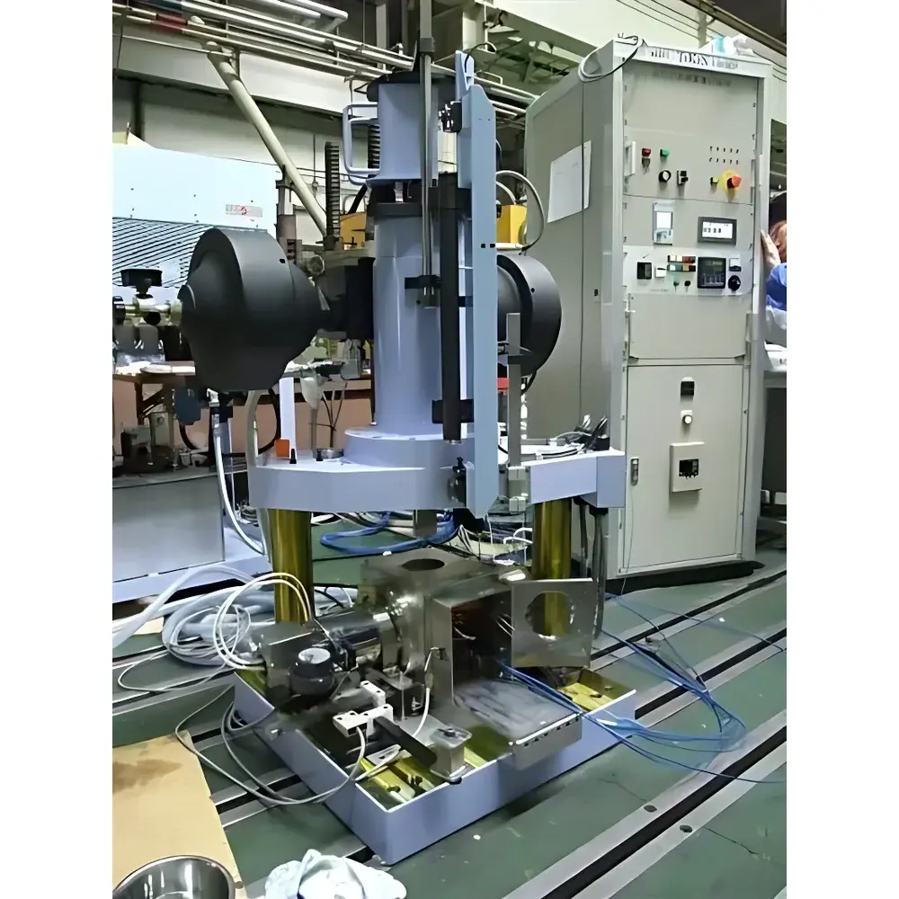
High-Speed Impact Testing Machine (Hydraulic Servo Type)
| Key | Origin: Japan |
|---|---|
| Manufacturer Type | Distributor |
| Origin Category | Imported |
| Model | High-Speed Impact Testing Machine (Hydraulic Servo Type) |
| Pricing | Upon Request |
| Max Impact Energy | 5250 J |
| Rated Specimen Absorption Energy | 4500 J |
| Rated Specimen Reaction Force | ±400 kN |
| Loading Velocity Range | ±2 to ±10 m/s |
Overview
The High-Speed Impact Testing Machine (Hydraulic Servo Type) is an advanced dynamic mechanical testing system engineered for precise, repeatable, and controllable high-velocity impact evaluation of structural and functional materials. Unlike conventional drop-weight or pendulum-based impact testers, this system employs a closed-loop hydraulic servo architecture—integrating a high-capacity energy storage accumulator, ultra-fast-response proportional servo valves, and a rigid load frame—to deliver programmable compressive or tensile impact loading with sub-millisecond timing resolution. Its fundamental operating principle relies on controlled hydraulic actuation to accelerate a massive impact ram to velocities ranging from ±2 m/s to ±10 m/s, enabling direct measurement of force–displacement–time histories under well-defined boundary conditions. This capability supports quantitative characterization of strain-rate-dependent mechanical behavior—including yield strength, fracture toughness, energy absorption efficiency, and dynamic modulus—critical for validating material performance in safety-critical infrastructure and high-integrity components.
Key Features
- Hydraulic servo-driven impact actuation ensures full control over velocity profile, peak load, and dwell time—eliminating the stochastic variability inherent in gravity-driven systems.
- Low-profile installation footprint (<2.5 m height), enabled by elimination of elevated drop towers; ideal for constrained laboratory spaces and integration into cleanroom or shielded test bays.
- Integrated high-bandwidth load cell (±400 kN rated reaction force) and optical displacement encoder provide synchronized, high-fidelity acquisition of dynamic response data at sampling rates up to 1 MHz.
- Energy recovery circuitry minimizes thermal drift during sequential testing, maintaining system stability across extended test campaigns.
- Modular fixture interface accommodates standardized specimen geometries (e.g., ASTM E2298, ISO 13473-1) as well as custom-designed fixtures for complex component-level validation.
Sample Compatibility & Compliance
The system is validated for testing metallic alloys, fiber-reinforced polymer composites (including CFRP and GFRP), concrete specimens, welded joints, and safety-critical elastomeric isolators. Specimen dimensions are configurable within standard ranges (up to 300 mm × 300 mm × 150 mm). All hardware and firmware comply with IEC 61000-6-2 (EMC immunity) and ISO 12100 (functional safety of machinery). Test protocols align with ASTM E2298 (Standard Test Method for Dynamic Tensile Properties of Plastics Using a Split Hopkinson Tensile Bar), ISO 148-1 (Metallic materials — Charpy pendulum impact test), and JIS Z 2242 (Impact testing of metals). Data acquisition and reporting support audit-ready traceability per GLP and GMP requirements, including timestamped metadata, operator ID logging, and electronic signature fields compliant with FDA 21 CFR Part 11.
Software & Data Management
The proprietary control and analysis suite runs on a real-time Windows OS platform with deterministic kernel scheduling. It provides intuitive waveform configuration (ramp, trapezoidal, or user-defined velocity profiles), live monitoring of hydraulic pressure, ram position, and load feedback, and automated pass/fail assessment against preloaded acceptance criteria. Raw data is exported in HDF5 format with embedded calibration coefficients and environmental metadata (temperature, humidity, oil viscosity). Post-processing modules include Fourier-based spectral analysis, energy partitioning (elastic/plastic/fracture dissipation), and comparative strain-rate binning. All software updates and calibration certificates are digitally signed and version-controlled via secure TLS-encrypted repository access.
Applications
This instrument serves mission-critical applications across nuclear power plant component qualification (e.g., seismic isolation bearings, containment liner anchorage systems), transportation infrastructure resilience testing (bridge expansion joints, rail crash barriers), automotive passive safety development (crash rails, battery enclosure impact shields), and advanced composite certification (CFRP fuselage sections, wind turbine blade root joints). It is routinely deployed in R&D labs supporting ASME Section III, RCC-M, and EN 15085-2 compliance verification, where reproducible high-strain-rate data informs finite element model validation and probabilistic risk assessment frameworks.
FAQ
What distinguishes hydraulic servo impact testing from traditional drop-weight methods?
Hydraulic servo systems enable precise control of impact velocity, force ramp rate, and loading direction—both compression and tension—without reliance on gravitational acceleration or mechanical release mechanisms.
Can the system perform repeated impact sequences at varying strain rates?
Yes. The accumulator-based energy delivery and fast-cycling servo valves allow up to 120 impact events per hour with programmable inter-test cooling intervals and automatic recalibration checks.
Is third-party calibration and traceability available?
All load cells and displacement sensors are NIST-traceable and supplied with UKAS-accredited calibration certificates; annual verification services are supported globally through authorized service partners.
Does the system meet nuclear industry QA requirements?
Yes. Full documentation packages—including FAT/SAT reports, IQ/OQ/PQ protocols, and cybersecurity hardening logs—are provided to support ASME NQA-1 and ISO 19443 implementation.
What maintenance intervals are recommended for sustained high-energy operation?
Hydraulic fluid analysis and filter replacement every 500 operational hours; accumulator precharge verification and valve response diagnostics every 1,000 hours—detailed in the OEM Preventive Maintenance Manual (Rev. 4.2).


