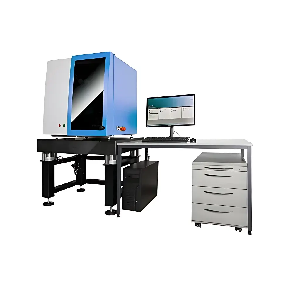
Jenoptik FLEX-3A Modular Structured-Light 3D Scanner
| Brand | Jenoptik |
|---|---|
| Origin | Germany |
| Model | FLEX-3A |
| Type | Photogrammetry-Assisted Structured-Light 3D Scanner |
| Max Scanning Range (L×W) | 20 mm × 15 mm to 230 mm × 172 mm |
| Measurement Point Resolution | <10 µm |
| Compliance | VDI/VDE 2634 Part 3 (Accuracy Validation), PTB/NIST-Traceable Calibration Protocol |
| Standard Calibration Artifact | Spherical Dumbbell Reference Standard (Included) |
| Software Platform | OTTO Vision CVS (Certified for GLP/GMP Traceability & Audit Trail per FDA 21 CFR Part 11) |
Overview
The Jenoptik FLEX-3A is a modular, high-precision structured-light 3D scanning system engineered for metrology-grade geometric inspection in R&D laboratories, precision manufacturing QA/QC environments, and tooling validation workflows. It operates on a hybrid photogrammetric–triangulation principle: calibrated multi-camera arrays project precisely encoded fringe patterns onto the object surface, while synchronized high-resolution sensors capture deformation of these patterns. The resulting dense point cloud—reconstructed via robust phase-shifting algorithms—is registered with sub-pixel accuracy against a photogrammetric reference frame established by fixed fiducial markers. This dual-reference architecture ensures traceable dimensional fidelity across varying field-of-view configurations and eliminates cumulative registration error during multi-station scans. Designed for compliance-critical applications, the FLEX-3A meets the stringent repeatability and uncertainty requirements defined in VDI/VDE 2634 Part 3 for optical 3D coordinate measuring systems, with factory calibration validated using a certified spherical dumbbell artifact included in every shipment.
Key Features
- Modular optical head configuration: Select from nine standardized measurement volumes (20 mm × 15 mm to 230 mm × 172 mm), each optimized for specific part size and surface complexity.
- Sub-10 µm measurement point resolution at nominal working distance, achieved through high-contrast sinusoidal fringe projection and 12-bit CMOS imaging sensors.
- Dual-axis automated rotation stage with ±70 mm linear Z-axis extension option for full 360° + top/bottom coverage of tall or asymmetric components.
- Integrated flip-mount reference fixture enabling automatic alignment of upper and lower surfaces without manual repositioning—critical for thin-walled or symmetric parts.
- Four-camera extended-field kit available as optional upgrade to increase depth-of-field coverage and reduce occlusion in complex undercuts.
- Real-time fringe pattern optimization engine dynamically adjusts exposure time, intensity, and phase step count based on local surface reflectivity and curvature.
Sample Compatibility & Compliance
The FLEX-3A accommodates diverse material classes—including polished metals, matte plastics, anodized aluminum, and painted composites—without requiring spray-based contrast enhancement, thanks to adaptive illumination control and spectral filtering. Its mechanical design supports sample weights up to 5 kg and heights up to 200 mm when configured with the extended Z-axis. All delivered systems undergo final acceptance testing per VDI/VDE 2634 Part 3 using the supplied spherical dumbbell standard; measurement uncertainty budgets are documented in the Certificate of Conformance. For regulated industries, the integrated CVS software provides full audit trail functionality—including user login logs, parameter change history, report generation timestamps, and electronic signatures—fully compliant with FDA 21 CFR Part 11 and EU Annex 11 requirements. Traceability to PTB and NIST primary standards is maintained through annual recalibration services supported by Jenoptik’s global metrology network.
Software & Data Management
OTTO Vision’s CVS software serves as the unified platform for acquisition, evaluation, and reporting. It supports fully parametrized measurement plans—defining camera positions, lighting parameters, fringe frequency, number of phase shifts, and motion sequencing—with version-controlled storage. Automated alignment routines include RPS-based fitting (3-2-1, best-fit global/local, feature-constrained), cross-sectional slicing, wall-thickness analysis, and GD&T evaluation per ISO 1101. Color-mapped deviation overlays (actual-vs-CAD) are exportable in HTML, PDF, and XML formats. Raw point clouds and polygonal meshes (STL, PLY) can be exported directly into CATIA, Siemens NX, or Geomagic Design X; parametric CAD reconstruction is enabled via automatic surface classification (planes, cylinders, spheres, tori) and NURBS patch generation from triangulated models. All data files embed EXIF metadata containing calibration ID, environmental conditions (temperature/humidity), and operator credentials.
Applications
- First-article inspection of injection-molded housings, turbine blades, and medical device components against nominal CAD geometry.
- Tool wear monitoring in die-casting and forging dies via periodic 3D surface comparison over production cycles.
- Reverse engineering of legacy parts lacking original CAD data—generating STEP/IGES models suitable for CNC programming or additive manufacturing.
- Surface defect detection and quantification (scratches, dents, porosity) using curvature gradient analysis and height-map thresholding.
- Geometric tolerance verification (flatness, cylindricity, position, concentricity) on machined aerospace fittings and automotive powertrain assemblies.
- Non-contact thickness mapping of composite laminates and battery cell casings where contact probes risk damage or distortion.
FAQ
What calibration standards are included with the FLEX-3A?
A certified spherical dumbbell reference artifact is supplied with each system, enabling in-house verification of volumetric accuracy per VDI/VDE 2634 Part 3.
Is the system compatible with existing metrology workflows in ISO 17025-accredited labs?
Yes—the FLEX-3A’s uncertainty budget, traceable calibration chain, and CVS software audit trail meet ISO/IEC 17025 documentation requirements for accredited testing laboratories.
Can the scanner handle highly reflective or transparent surfaces without coating?
The system incorporates dynamic polarization control and multi-spectral fringe projection to suppress specular glare on polished metals; translucent polymers require minimal matte spray only in edge-case scenarios.
How is multi-view alignment performed between non-overlapping scan regions?
Photogrammetric marker tracking across all views establishes a common coordinate frame prior to point cloud fusion—eliminating reliance on surface-based iterative closest point (ICP) algorithms.
Does the software support automated pass/fail reporting aligned with PPAP or APQP requirements?
CVS includes configurable report templates with embedded GD&T callouts, statistical process capability indices (Cp/Cpk), and digital signature fields compliant with AIAG PPAP Level 3 submission standards.