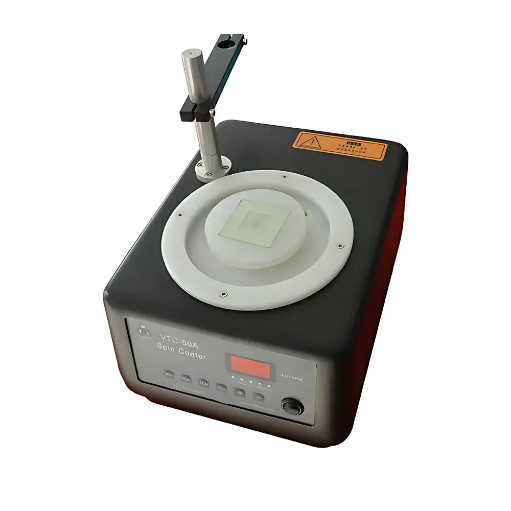
KJ GROUP VTC-50A Spin Coater
| Brand | KJ GROUP |
|---|---|
| Origin | Liaoning, China |
| Manufacturer Type | Authorized Distributor |
| Country of Origin | China |
| Model | VTC-50A |
| Price | USD 1 (FOB Inquiry Basis) |
| Power Supply | AC 220/110 V, 50/60 Hz |
| Max. Speed | 8000 rpm |
| Speed Stability | ±1% |
| Speed Range (SPD1 & SPD2) | 500–8000 rpm |
| Time Range (T1 & T2) | 1–60 s each |
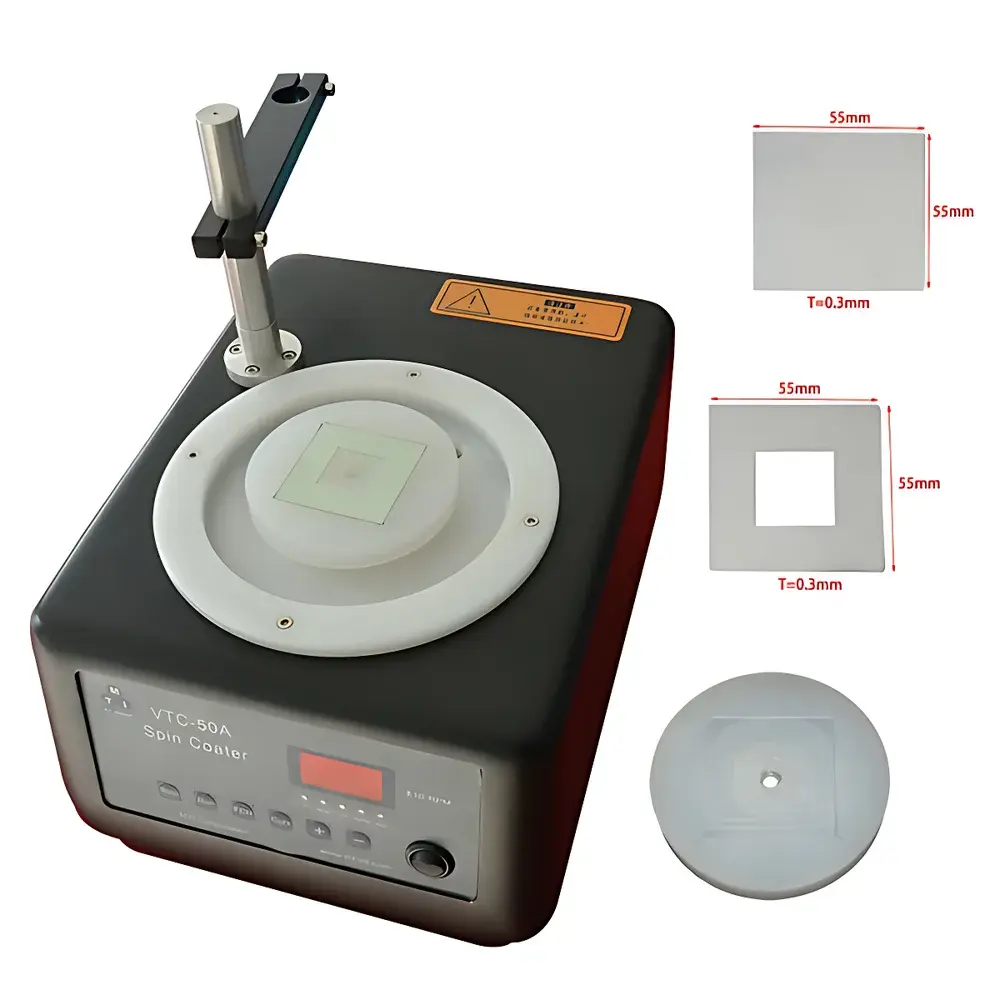
| Sample Holder | Polypropylene Chuck, Ø100 mm |
| Dimensions | 260 × 380 × 330 mm |
| Weight | 12 kg |
| Operating Temp. | 0–45 °C |
| Humidity | 10–85% RH (non-condensing) |
| Control System | Embedded MCU with Keypad & 7-Segment Display |
| Rotation Direction | Counter-clockwise |
| Power Consumption | ≤150 W |
Overview
The KJ GROUP VTC-50A Spin Coater is an engineered benchtop instrument designed for reproducible, controlled thin-film deposition via rotational shear-driven fluid thinning—a fundamental technique widely adopted in materials science, semiconductor research, and optoelectronic device fabrication. Based on the principle of centrifugal force-induced radial thinning, the VTC-50A accelerates liquid or viscous precursors (e.g., sol-gel solutions, polymer resins, photoresists, perovskite inks) across a stationary substrate to achieve uniform film thickness governed by angular velocity, solution viscosity, surface tension, and spin duration. Its dual-stage programmable protocol—comprising low-speed dispensing (SPD1/T1) followed by high-speed spreading (SPD2/T2)—mimics industry-standard spin-coating workflows used in cleanroom-compatible R&D environments. The system operates without vacuum chucks or adhesive fixtures, relying instead on mechanical retention via a precision-machined polypropylene chuck with user-customizable cutouts, ensuring zero substrate deformation and compatibility with brittle, flexible, or non-conductive wafers and slides.
Key Features
- Two-stage programmable spin protocol (SPD1/T1 + SPD2/T2) enables precise control over precursor wetting and film leveling—critical for minimizing edge beads, coffee-ring effects, and thickness gradients.
- Embedded microcontroller-based speed regulation delivers ±1% rotational stability across the full 500–8000 rpm range, validated under load and thermal equilibrium conditions.
- Polypropylene sample chuck (Ø100 mm) features modular slot templates; users can cut custom apertures (e.g., square, circular, rectangular) directly into supplied acrylic or resin base plates—no vacuum pumps, clamps, or UV-curable adhesives required.
- Decoupled power architecture isolates motor and control circuitry, reducing electromagnetic interference and enhancing long-term signal integrity in shared lab environments.
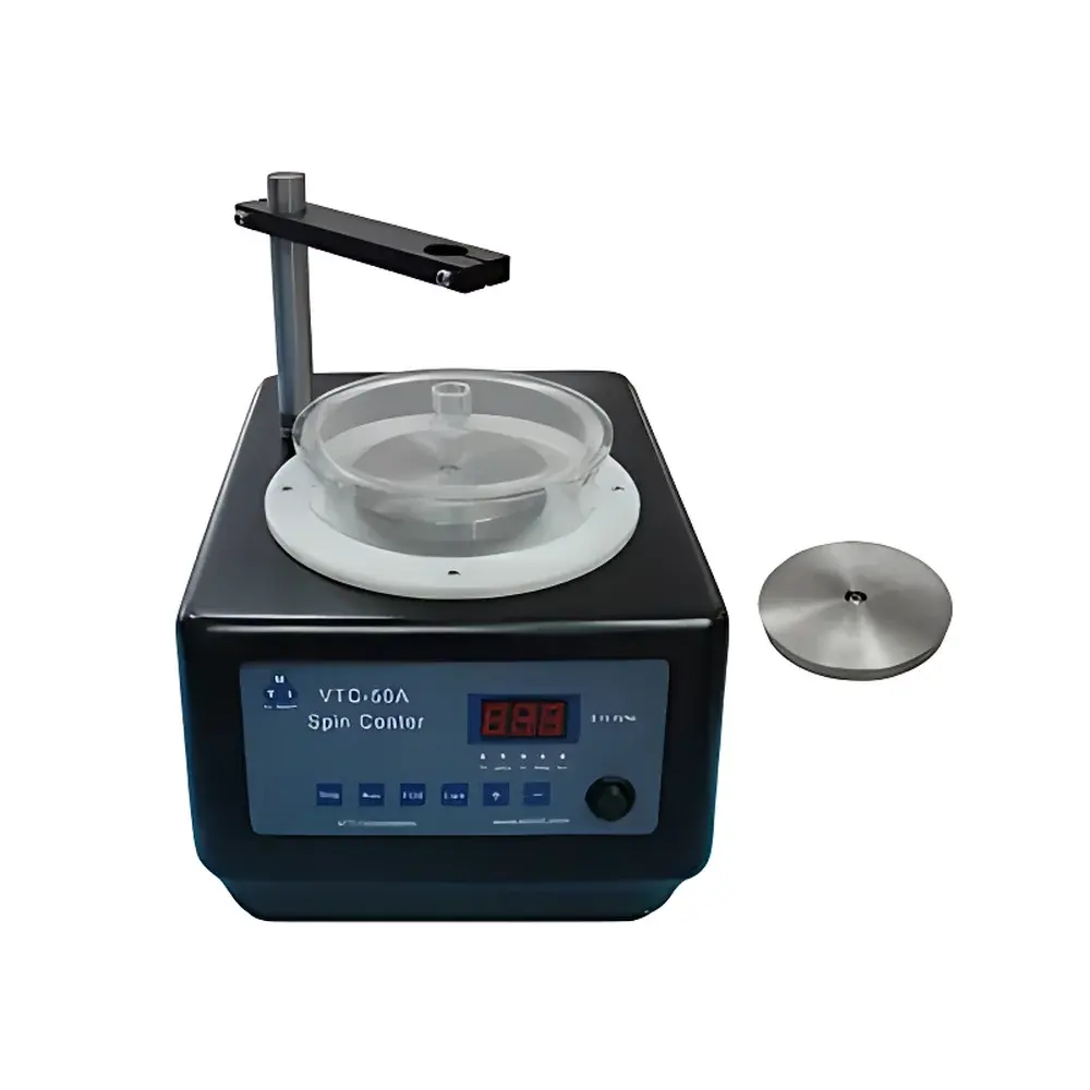
- Acrylic transparent lid and die-cast aluminum chassis provide structural rigidity, acoustic damping, and real-time visual monitoring without compromising safety or particulate containment.
- English-language UI with 7-segment LED display and tactile keypad ensures intuitive operation across international academic and industrial labs—no software installation or driver dependencies.
Sample Compatibility & Compliance
The VTC-50A accommodates rigid and semi-flexible substrates up to 100 mm in diameter—including silicon wafers (1″, 2″, 3″), glass slides (25 × 75 mm, 55 × 55 mm), ITO/PET films, ceramic tiles, and metal foils—without requiring surface metallization or backside treatment. Its chuck design complies with standard ISO 7807 (thin-film preparation procedures) and supports method transfer to production-scale spin coaters referenced in ASTM D1239 (coating thickness uniformity testing). While not certified for GMP manufacturing, the instrument’s traceable speed/time parameters, stable mechanical architecture, and absence of consumables (e.g., O-rings, vacuum lines) support GLP-aligned documentation practices. All electrical components meet IEC 61010-1 safety requirements for laboratory equipment; grounding continuity and insulation resistance are verified per factory calibration protocols.
Software & Data Management
The VTC-50A operates as a standalone hardware controller with no embedded firmware update capability or network interface. All operational parameters—SPD1, T1, SPD2, T2—are entered manually and retained in volatile memory until power cycle. For auditability, users are advised to record settings alongside batch identifiers in external lab notebooks or LIMS systems. Though no digital data export is supported, the ±1% speed tolerance and 1-second time resolution allow direct correlation with theoretical film thickness models (e.g., Meyerhofer equation) for process qualification. When integrated into regulated environments, manual log entries may be supplemented with timestamped video capture (via external camera) to satisfy FDA 21 CFR Part 11 “contemporaneous record” expectations for non-electronic systems.
Applications
- Preparation of uniform photoresist layers for maskless lithography prototyping in university cleanrooms.
- Deposition of metal oxide precursor films (e.g., TiO₂, ZnO) for dye-sensitized and perovskite solar cell research.
- Coating of conductive polymer dispersions (PEDOT:PSS) onto flexible PET substrates for printed electronics studies.
- Spin-casting of quantum dot inks for emissive layer formation in OLED test structures.
- Rapid screening of solvent evaporation kinetics and solidification behavior in colloidal nanomaterial suspensions.
- Teaching laboratory demonstrations of Newtonian/non-Newtonian fluid behavior under transient centrifugal fields.
FAQ
Does the VTC-50A support vacuum chucking or optional vacuum accessories?
No. The system relies exclusively on mechanical retention using the polypropylene chuck and custom-cut templates. Vacuum chucks are neither included nor available as add-ons.
Can the rotation direction be reversed to clockwise?
No. The motor is fixed for counter-clockwise rotation only, consistent with standard spin-coating conventions in semiconductor processing.
Is the unit compatible with 110 V / 60 Hz power supplies used in North America?
Yes—the built-in power input accepts AC 110–220 V, 50–60 Hz; users must select appropriate fuse (10 A, φ5 × 20 mm) and verify local outlet grounding compliance.
What is the maximum substrate thickness the chuck can accommodate?
The standard chuck accepts substrates up to 3 mm thick; thicker samples may require custom template modification to ensure full peripheral contact and centering stability.
Are calibration certificates or metrology reports provided with shipment?
Factory speed verification is performed at three points (1000, 4000, and 8000 rpm) using a traceable optical tachometer; formal NIST-traceable calibration documentation is available upon request at additional cost.


