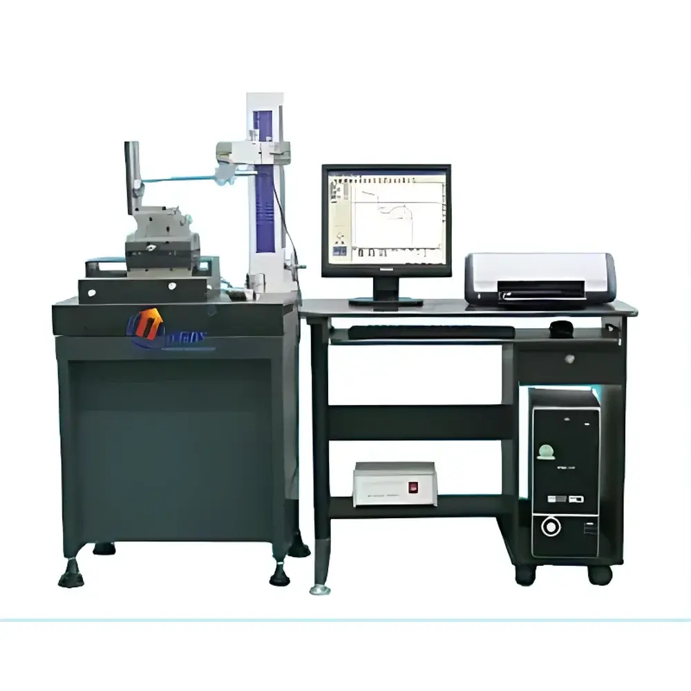
MC012-XZ-150G Precision Contour Profilometer
| Origin | China |
|---|---|
| Manufacturer Type | Authorized Distributor |
| Product Category | Domestic |
| Model | MC012-XZ-150G |
| Quotation | Upon Request |
| Z-Axis Linear Motion Accuracy | ≤0.2 µm / 100 mm |
| X-Axis Grating Resolution | ≤3 µm / 150 mm |
| Sensor Range | 6 mm (expandable) |
| Maximum Workpiece Diameter | Ø100 mm (shaft), Ø200 mm (sleeve) |
| Effective Measurement Length | 140 mm |
| Air Bearing Stage | Closed-type Pneumatic Float |
| Traverse Speed | 0.2–0.4 mm/s (3-step mechanical speed control) |
| Power Supply | 220 V, 50 Hz, 0.5 kW |
| Clean Air Requirement | ≥0.5 MPa |
Overview
The MC012-XZ-150G Precision Contour Profilometer is an advanced contact-type geometric metrology instrument engineered for high-resolution profile and form measurement of machined components. Based on high-stability closed-loop pneumatic bearing translation stages and precision linear optical grating feedback, it delivers traceable, repeatable contour data in accordance with ISO 1101 (Geometrical Product Specifications – Geometrical tolerancing) and ISO 5436-1 (Profile measurement standards). The system employs a vertically mounted stylus-based displacement sensor with 6 mm full-scale range to capture surface topography along the Z-axis, while the X-axis carriage enables precise lateral scanning over 150 mm travel. Its design targets routine quality control in bearing manufacturing, precision machining, and automotive component production—where parameters such as straightness, parallelism, angular deviation, circularity, radial runout, groove geometry (width, depth, center-to-center spacing), and tangent-line-to-arc relationships must be quantified under workshop or lab-grade environmental conditions.
Key Features
- Closed-type pneumatic air bearing stage ensures long-term motion stability, minimal friction hysteresis, and sub-micron positional repeatability over extended operational life.
- High-accuracy linear optical grating encoder (X-axis resolution ≤3 µm over 150 mm) provides robust position feedback independent of mechanical wear or thermal drift.
- Integrated Windows-based proprietary measurement software offers intuitive graphical interface, real-time profile rendering, and one-click report generation compliant with internal QA documentation protocols.
- Full-degree arbitrary profile rotation enables alignment-independent evaluation—critical for assessing features referenced to non-principal axes or custom datums.
- Comprehensive error compensation algorithms correct for stylus tip geometry, vertical tilt, stage bow, and thermal expansion effects—enhancing measurement fidelity without requiring external calibration artifacts for every setup.
- Dedicated modular fixturing system supports rapid mounting and alignment of shafts (Ø1–100 mm), sleeves (≤Ø200 mm), and stepped components up to 140 mm in length.
- Three-step mechanical traverse speed control (0.2–0.4 mm/s) allows optimization between measurement throughput and signal-to-noise ratio across varying surface finishes and feature densities.
Sample Compatibility & Compliance
The MC012-XZ-150G accommodates a broad spectrum of metallic and ceramic workpieces typical in rolling element bearing assemblies—including inner/outer rings, rollers, cages, and raceways—as well as general-purpose machined parts such as camshafts, hydraulic spools, and precision bushings. It conforms to dimensional inspection requirements outlined in ISO 4287 (Surface roughness – Parameters), ISO 12181 (Roundness), and ANSI/ASME B89.3.1M (Coordinate measuring machines and systems). While not certified for FDA 21 CFR Part 11 out-of-the-box, its audit-ready data logging architecture—including timestamped raw profiles, operator ID tagging, and version-controlled report templates—supports validation under GLP and GMP frameworks when deployed within controlled laboratory environments.
Software & Data Management
The instrument operates via a dedicated Windows 10-compatible application that supports Unicode file naming, CSV/Excel export of coordinate point clouds (X, Z, curvature, slope), and PDF report generation with embedded metrology annotations. All measurement sessions are automatically archived with metadata (date/time, operator, part ID, fixture configuration, environmental notes). Software includes built-in GD&T evaluation modules for straightness, flatness, circularity, concentricity, and profile of a line—each computed per ASME Y14.5–2018 definitions. Audit trail functionality records parameter changes, report edits, and user login/logout events, facilitating compliance with internal quality system requirements and third-party assessments.
Applications
- Quantitative assessment of raceway curvature deviation and waviness in tapered roller bearings.
- Verification of groove symmetry, flank angle, and root radius in ball bearing inner/outer rings.
- Measurement of taper angle, conicity, and axial runout on precision shafts and spindles.
- Analysis of cam lobe lift profiles, dwell zones, and transition radii in engine valve train components.
- Validation of gear blank tooth seat geometry prior to hobbing or grinding operations.
- Comparative analysis of wear-induced profile changes in service-tested components using baseline archival data.
FAQ
What is the maximum measurable diameter for cylindrical parts?
The system supports shafts up to Ø100 mm and sleeves or flanged components up to Ø200 mm.
Can the sensor range be extended beyond 6 mm?
Yes—the standard sensor is field-upgradable to 10 mm or 15 mm ranges using factory-calibrated transducers; contact technical support for compatibility verification.
Is the instrument compatible with automated shop-floor integration?
While primarily designed for manual operation, the software exposes COM/ActiveX interfaces enabling programmatic control and data ingestion into MES or SPC platforms via custom scripts.
Does the system require periodic recalibration by an accredited lab?
Annual verification against NIST-traceable step gauges or certified radius artifacts is recommended; full recalibration is required if mechanical impact, air supply contamination, or grating damage is suspected.
What environmental conditions are recommended for optimal performance?
Stable ambient temperature (20 ± 1 °C), humidity <60% RH, and vibration isolation (ISO 230-2 Class 3 or better) are advised to maintain stated Z-axis accuracy specifications.