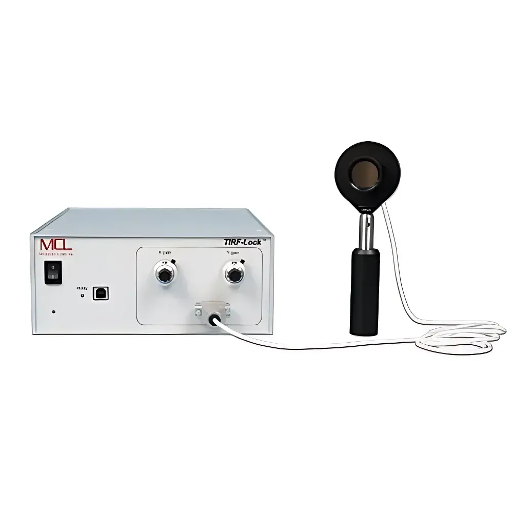
MCL Think Nano TIRF Lock™ Autofocus System
| Brand | MCL Think Nano |
|---|---|
| Origin | USA |
| Manufacturer Type | Authorized Distributor |
| Product Category | Imported Instrument |
| Model | TIRF Lock™ |
| Instrument Type | Inverted Fluorescence Microscope Add-on Module |
| Excitation Source | Metal Halide Lamp |
| Eyepiece | Standard |
| Objective | Standard |
| Fluorescence Configuration | Epi-Fluorescence |
| Compatible Light Sources | Any Illumination Source |
| Observation Head | Inverted |
| Wavelength Range | 400–1000 nm |
| Peak Responsivity | 0.4 A/W @ 635 nm, 0.67 A/W @ 900 nm |
| Recommended Input Beam Diameter | 300 µm – 1.5 mm |
| Sensor Active Area | 2.4 mm × 2.4 mm |
| Clear Aperture | 12.5 mm (0.5 inch) |
| Aperture Threading | SM05 (0.535-40) |
| Detector Head Mounting Thread | 8-32 or M4 |
| Base Mounting Thread | 1/4-20 or M6 (magnetic base & clamping fork included) |
| Detector Cable Length | 1.83 m (6 ft) |
| Power Supply | 90–260 V AC |
| Controller Dimensions | 212.7 mm × 88.9 mm × 304.8 mm (8.375″ × 3.5″ × 12″) |
| PC Interface | USB 2.0 |
| OS Compatibility | Windows XP Pro / Vista / 7 / 8 (32- or 64-bit) |
Overview
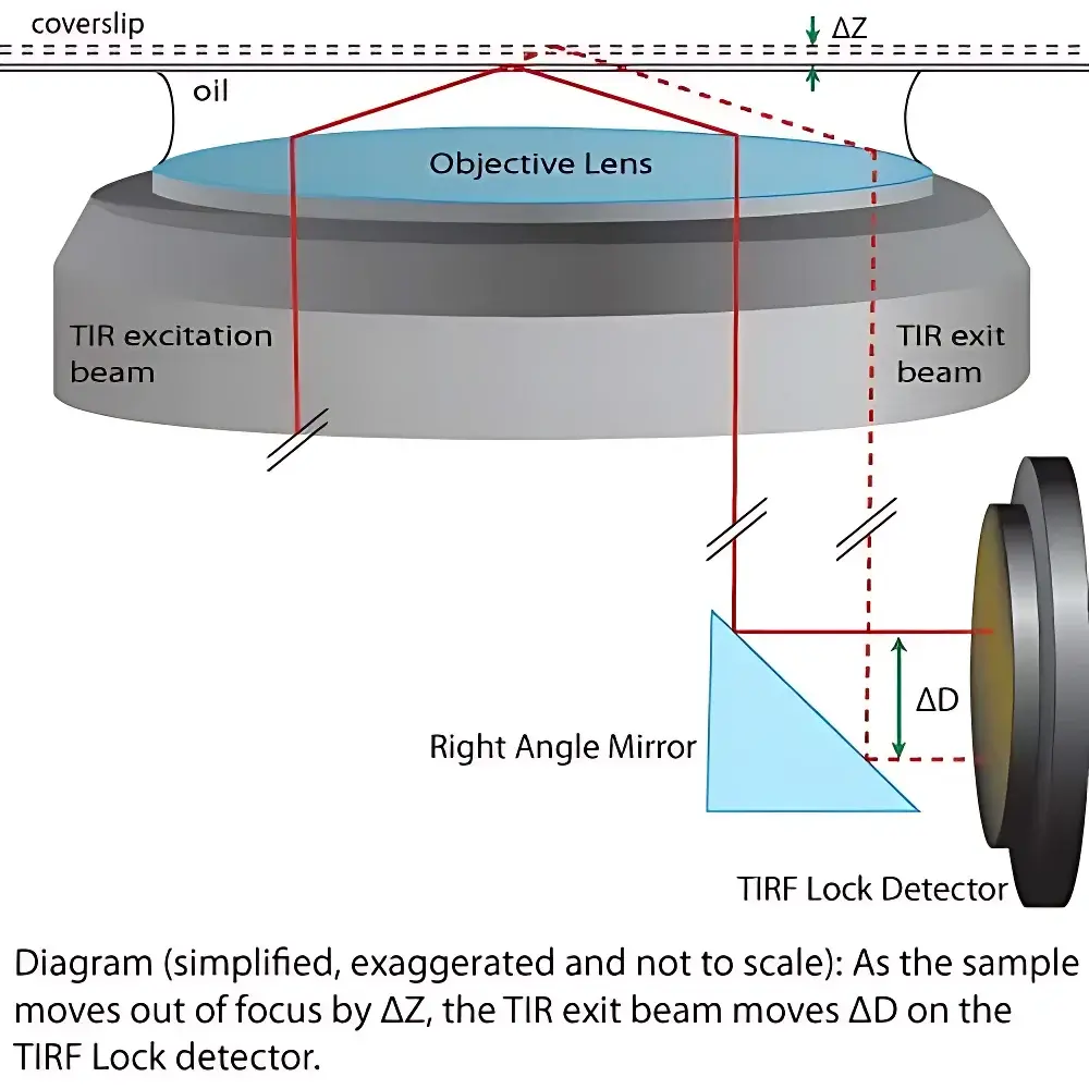
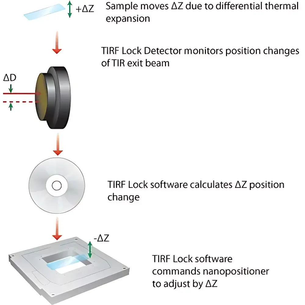
The MCL Think Nano TIRF Lock™ is a high-stability, closed-loop autofocus system engineered specifically for total internal reflection fluorescence (TIRF) microscopy applications requiring sub-nanometer axial position stability over extended acquisition periods. Unlike conventional focus drift compensation methods based on image contrast or infrared reflection, the TIRF Lock™ operates on a direct optical feedback principle: it monitors minute lateral displacements of the evanescent field’s exit beam—caused by thermal expansion, mechanical creep, or stage drift—and translates them into real-time Z-axis correction signals for compatible nanopositioners. This physical measurement approach ensures robustness against sample photobleaching, fluorophore saturation, or heterogeneous refractive index changes that commonly degrade intensity-based autofocus algorithms. The system integrates seamlessly into inverted fluorescence microscope platforms where precise control of the evanescent illumination angle is critical—enabling stable single-molecule imaging, live-cell membrane dynamics studies, and quantitative colocalization experiments under physiological conditions.
Key Features
- Real-time, non-invasive beam displacement sensing via quadrant photodiode (QPD) head with <1 nm positional resolution in Z-feedback loop
- Native compatibility with Mad City Labs RM21™ microscope frames, MicroMirror TIRF systems, and third-party TIRF modules using standard optical coupling interfaces
- Full integration with MCL’s XYZ nanopositioning stages (e.g., Nano-Drive™ series) for synchronized Z-correction and multi-axis stabilization
- LabVIEW-based VI software with configurable PID parameters, logging capabilities, and real-time beam position visualization
- Broad spectral response (400–1000 nm) supporting common TIRF excitation wavelengths including 405 nm, 488 nm, 561 nm, 640 nm, and 900 nm NIR-TIRF configurations
- Modular mechanical design featuring SM05-threaded aperture, dual mounting options (8-32/M4 detector head + 1/4-20/M6 base), and included magnetic base/clamping fork for rapid alignment
Sample Compatibility & Compliance
The TIRF Lock™ imposes no intrinsic constraints on sample type, thickness, or mounting medium—its operation is independent of specimen optical properties. It functions equally well with glass-bottom dishes, fused-silica coverslips, microfluidic chambers, and organoid culture platforms. From a regulatory standpoint, the system supports GLP/GMP-aligned workflows through its deterministic, physics-based feedback architecture and audit-ready LabVIEW VI logging (timestamped position data, error residuals, and control output). While not FDA-cleared as a medical device, its design adheres to IEC 61000-6-3 (EMC emissions) and IEC 61010-1 (safety for laboratory equipment) standards. Data integrity complies with ALCOA+ principles when used in conjunction with validated LabVIEW environments meeting 21 CFR Part 11 requirements for electronic records and signatures.
Software & Data Management
The TIRF Lock™ controller communicates exclusively via USB 2.0 to a host PC running Windows XP through Windows 8 (32-/64-bit). Its native LabVIEW Virtual Instrument provides a minimal GUI for initial calibration, gain tuning, and real-time monitoring of QPD quadrant voltages and calculated centroid position. All operational parameters—including proportional/integral/derivative coefficients, sampling rate (default 100 Hz), and Z-offset reference—are stored in human-readable XML configuration files. Raw sensor data and correction trajectories can be exported in CSV format for post-acquisition analysis in MATLAB, Python (NumPy/Pandas), or Igor Pro. No cloud connectivity or proprietary runtime dependencies are required; the VI runs natively without additional drivers beyond NI-VISA and LabVIEW Runtime Engine v12.0 or later.
Applications
- Long-duration single-molecule TIRF imaging of actin polymerization, kinesin motility, or DNA-protein interactions
- Live-cell plasma membrane trafficking assays using pH-sensitive or lipid-anchored probes
- High-resolution co-tracking of receptor-ligand binding events at the basal surface of polarized epithelial cells
- Quantitative HILO (highly inclined and laminated optical sheet) microscopy requiring stable oblique illumination geometry
- Correlative TIRF–AFM or TIRF–STORM experiments where nanoscale Z-registration between modalities is essential
- Automated screening platforms integrating with motorized stage controllers for multi-position time-lapse TIRF acquisitions
FAQ
Does the TIRF Lock™ require modification of my existing microscope’s optical path?
No. It intercepts only the reflected or transmitted TIRF illumination beam downstream of the objective, using a pick-off mirror or dichroic splitter—no internal alignment or lens replacement is needed.
Can the system compensate for lateral (X/Y) drift as well as axial (Z) drift?
No. The TIRF Lock™ is designed exclusively for Z-axis stabilization via evanescent field geometry monitoring. Lateral drift correction requires separate hardware such as a piezo-driven stage or image-based tracking module.
Is LabVIEW development software required to operate the system?
No. The provided LabVIEW Runtime Engine suffices for full operation. Source code access is available under NDA for integration into custom acquisition pipelines.
What is the maximum allowable thermal drift rate the system can correct?
Under typical lab conditions (±0.5°C/h ambient fluctuation), the system maintains sub-5 nm RMS Z-stability over 60-minute acquisitions when paired with a MCL Nano-Drive™ Z-stage.
Does the controller support TTL triggering or synchronization with camera exposure signals?
Yes. The controller features two programmable digital I/O lines (opto-isolated) for external trigger input and status output, enabling frame-locked focus correction during camera readout intervals.