NexGen HB7044-2014 Aircraft Hose and Rigid Tube Assembly Flame Spread Tester
| Origin | USA |
|---|---|
| Supplier Type | Authorized Distributor |
| Origin Category | Imported |
| Model | HB7044-2014 |
| Pricing | Available Upon Request |
Overview
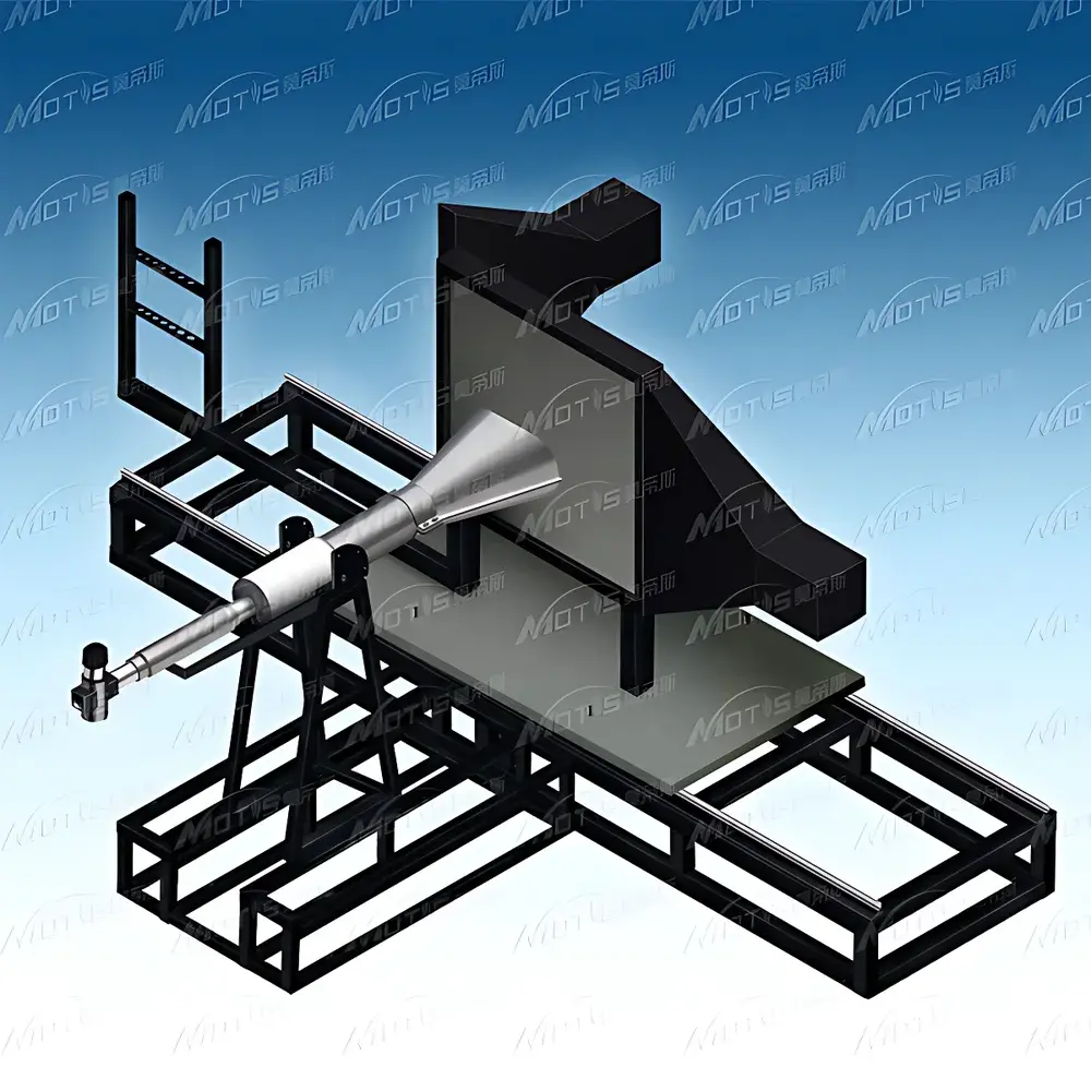
The NexGen HB7044-2014 Aircraft Hose and Rigid Tube Assembly Flame Spread Tester is a precision-engineered combustion test system designed to evaluate the flame propagation resistance of aerospace fluid conveyance components under standardized thermal exposure conditions. It operates on the principle of controlled, reproducible impingement of a high-intensity aviation fuel flame onto representative samples—such as flexible hoses, rigid metallic or composite tubing, electric motor housings, and electrical connector assemblies—simulating real-world fire exposure scenarios encountered during aircraft ground operations or in-flight emergencies. The system complies with critical aerospace fire safety standards including FAA AC 20-135, MIL-STD-202 Method 210, and most notably HB 7044–2014 (Chinese Civil Aviation Administration) and Chapter 12 of the FIRE TEST HANDBOOK. Its core function is to quantify flame spread rate, burn-through time, and post-exposure structural integrity—parameters directly linked to airworthiness certification requirements under EASA CS-25.853 and FAR Part 25 Subpart F.
Key Features
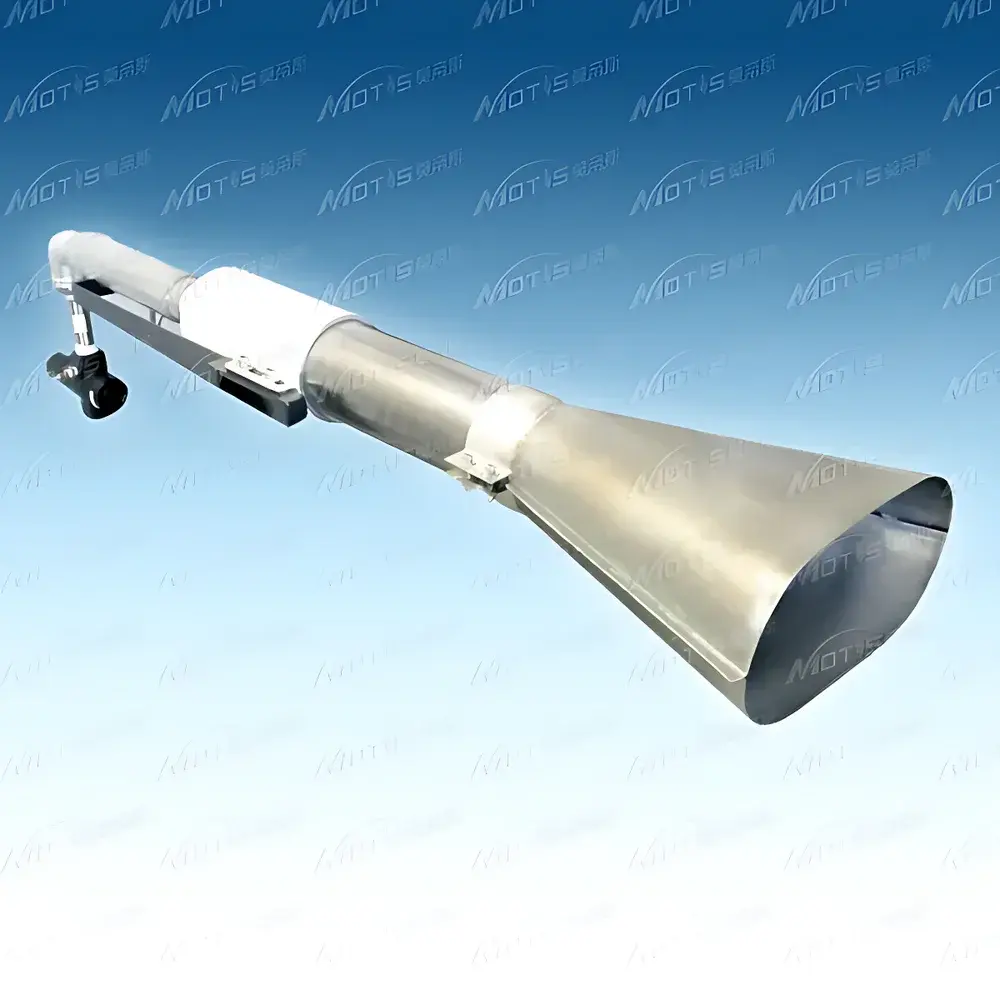
- NexGen proprietary aviation-grade kerosene (Jet A-1 equivalent) burner assembly featuring a corrosion- and high-temperature-resistant alloy conical nozzle, integrated turbulence-inducing baffle, precision-machined fuel injector, spark ignition module, dual-stage fuel rail, and acoustically damped housing with integrated silencer and acoustic impedance elements.
- Real-time monitoring and control of critical combustion parameters: fuel pressure (via calibrated Bourdon-tube gauge), fuel temperature (via RTD sensor), compressed air supply pressure (via adjustable regulator), and inlet air temperature (via thermistor array).
- Dual-phase thermal conditioning system comprising two insulated cryogenic baths (≥2 L each, ≥0.14 m³ volume per bath) for precise regulation of fuel temperature within ±1 °C across operational ranges from −20 °C to +60 °C.
- Adjustable air damper mechanism enabling fine-tuned volumetric airflow control at 1.89 ±0.05 m³/min (standardized at 25 °C, 101.3 kPa), ensuring consistent stoichiometric combustion and flame geometry.
- Fuel flow regulation via high-stability pressure-reducing valve capable of delivering nominal 0.126 L/min (±0.002 L/min) at specified inlet pressure, traceable to NIST-certified flow calibration protocols.
- Modular NexGen Burner Support System (BSS-1) providing mechanical stability, electrical grounding continuity, and interface compatibility with ASTM E136-compliant instrumentation racks.
- Heavy-duty structural steel frame engineered for both horizontal and vertical specimen mounting configurations, accommodating sample dimensions up to 1200 mm × 300 mm × 300 mm (L×W×H) with 3-point kinematic alignment.
- Integrated thermal insulation blanket system (ceramic fiber-based, 1260 °C rated) for localized shielding of non-test sections of fuel lines and aircraft fuselage mock-ups during qualification testing.
Sample Compatibility & Compliance
The tester accommodates a broad range of aerospace component geometries—including braided PTFE-lined hoses, aluminum and titanium rigid tubes, elastomeric gasketed couplings, and insulated wiring harnesses—with minimal fixture adaptation. All test procedures align with HB 7044–2014 Annex A (Flame Impingement Test), ASTM D635 (Horizontal Burning Rate), and ISO 6722–2 (Flammability of Automotive Wiring). Calibration is performed using a certified seven-element thermocouple comb: grounded-sheath K-type (NiCr–NiAl), 1.6 mm diameter ceramic-insulated probes, 30 AWG (0.254 mm OD, 0.0507 mm² cross-section, 361 Ω/km resistance) mounted on a precision-machined angle-iron fixture. Radiant heat flux is measured via water-cooled Gardon-type gauges (±2% full-scale accuracy) mounted on rigid cantilever brackets aligned perpendicular to flame axis. System validation meets GLP audit requirements per ISO/IEC 17025:2017 Clause 7.8.
Software & Data Management
Data acquisition is managed through a dedicated industrial PC running LabVIEW Real-Time OS with synchronized 16-channel analog input (24-bit resolution, 10 kHz sampling). All sensor readings—including thermocouple voltages, pressure transducer outputs, flow meter pulses, and radiant flux signals—are timestamped with GPS-synchronized UTC clocks and stored in HDF5 format compliant with ASTM E2500-22 Annex B. Audit trails include operator ID, calibration certificate numbers, environmental chamber logs (ambient T/RH), and digital signatures per FDA 21 CFR Part 11. Export modules support CSV, XML, and PDF report generation with embedded metadata for traceability in AS9100 Rev D quality systems.
Applications
- Qualification testing of hydraulic, pneumatic, and fuel line assemblies per CCAR-25.853 and EASA AMC 25.853.
- Fire resistance evaluation of electric propulsion cooling loops and battery interconnect tubing in hybrid-electric aircraft programs.
- Developmental validation of novel fluoropolymer composites and intumescent coatings for next-generation airframe fluid systems.
- Root cause analysis of in-service fire incidents involving hose burst or connector failure under thermal stress.
- Supporting DO-160 Section 24 (Fire Test) compliance documentation for avionics enclosure materials.
FAQ
What standards does the HB7044-2014 tester explicitly support?
It is configured and validated for HB 7044–2014, FIRE TEST HANDBOOK Chapter 12, MIL-STD-202 Method 210, and FAA AC 20-135 Appendix B.
Is the system compatible with Jet A, JP-5, and JP-8 fuels?
Yes—the burner design and fuel delivery subsystem are certified for all three specifications per MIL-DTL-83133F and ASTM D1655.
Can the system be integrated into an existing fire test laboratory’s data infrastructure?
Absolutely—it provides OPC UA server functionality and Modbus TCP interfaces for seamless integration with central LIMS or MES platforms.
What is the required maintenance interval for the thermocouple comb calibration?
Per ISO/IEC 17025, recalibration is mandated every 90 days or after 50 test cycles, whichever occurs first, using NIST-traceable dry-block calibrators.
Does the system include provisions for remote operation and safety interlocks?
Yes—fully redundant emergency stop circuits (Category 4 PL e per ISO 13849-1), flame-out detection via UV sensor, and Ethernet-based remote start/abort capability are standard.
Related Products


