
OETech HC-PBF Hollow-Core Photonic Bandgap Fiber
| Brand | OETech |
|---|---|
| Origin | Beijing, China |
| Manufacturer Type | Authorized Distributor |
| Product Category | Optical Component |
| Model | HC-PBF |
| Unit Price | USD 720 (FOB Beijing) |
| Core Material | Fused Silica |
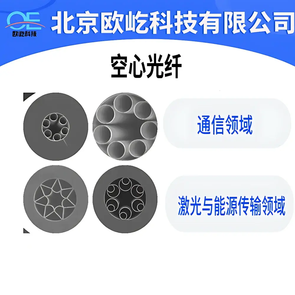
| Cladding Structure | Hexagonal Air-Hole Lattice |
| Coating | Single Acrylate |
| Bare Fiber Diameter | 145 µm |
| Coated Diameter | 360 µm |
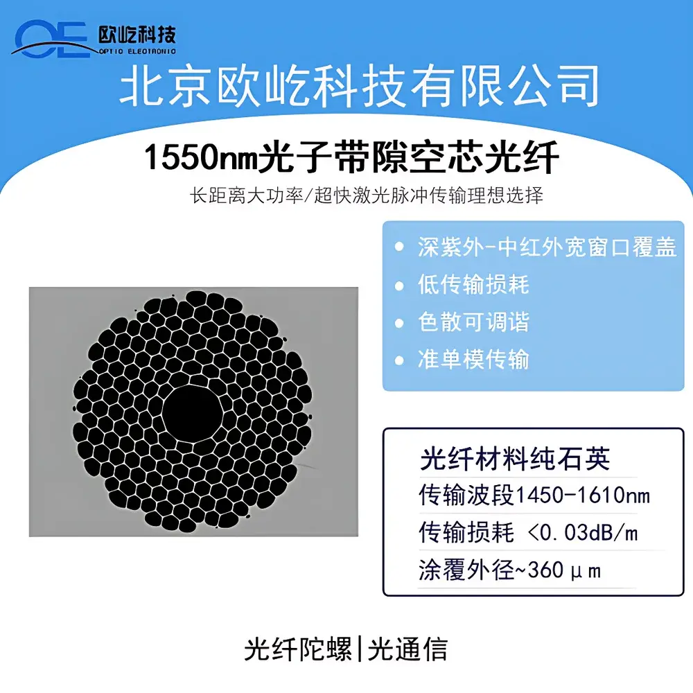
| Core Diameter | ~14 µm |
| Operating Wavelength Range | 1450–1610 nm |
| Attenuation | <0.03 dB/m |
| Minimum Loss | 0.011 dB/m @ 1570 nm |
| Loss at 1550 nm | 0.012 dB/m |
Overview
OETech HC-PBF Hollow-Core Photonic Bandgap Fiber is a precision-engineered optical component designed for advanced photonic research and high-performance laser delivery applications. Unlike conventional solid-core fibers relying on total internal reflection, the HC-PBF guides light via photonic bandgap confinement—where a periodic two-dimensional air-hole lattice in the silica cladding creates a spectral stopband that reflects guided modes within a defined wavelength window. This mechanism enables low-loss propagation of light predominantly within an air-filled core (~14 µm diameter), minimizing nonlinear effects, material absorption, and dispersion inherent to glass-core transmission. The fiber maintains standard telecom-compatible geometry (145 µm bare diameter, 360 µm acrylate-coated), ensuring seamless integration with existing fusion splicers, collimators, and connectorization systems. Its design adheres to fundamental principles of photonic crystal waveguide theory and is optimized for operation across the C- and L-bands (1450–1610 nm), with measured attenuation as low as 0.011 dB/m at 1570 nm.
Key Features
- True hollow-core guidance enabled by hexagonal photonic bandgap cladding architecture
- Ultra-low propagation loss: <0.03 dB/m across operational band; 0.012 dB/m at 1550 nm
- Air-core diameter of ~14 µm supports near-diffraction-limited beam quality and single-mode-like guidance
- Fused silica base material with high laser-induced damage threshold (LIDT > 10 GW/cm² for nanosecond pulses)
- Single acrylate coating ensures mechanical robustness while preserving bend-insensitive handling characteristics
- Compatible with standard SMF-28 splicing parameters using optimized arc discharge profiles
- No material dispersion dominance—group velocity dispersion (GVD) is primarily governed by waveguide geometry, enabling tailored pulse propagation
Sample Compatibility & Compliance
The HC-PBF is suitable for use in Class I and Class IIIB laser systems under IEC 60825-1:2014 compliance when integrated into properly engineered optical paths. Its all-silica construction meets RoHS Directive 2011/65/EU requirements. While not certified to ITU-T G.652.D or G.657.A1 standards due to its non-conventional guiding mechanism, the fiber’s geometric dimensions (core/clad concentricity, coating eccentricity < 5 µm) are controlled to within ±0.5 µm tolerance during draw tower fabrication—ensuring reproducible coupling efficiency and splice loss < 0.15 dB per joint under optimized conditions. For regulated environments (e.g., medical laser delivery per IEC 60601-2-22), system-level validation—including thermal stability testing at 25–70°C and humidity cycling (IEC 60068-2-30)—is required prior to deployment.
Software & Data Management
As a passive optical component, the HC-PBF does not incorporate embedded electronics or firmware. However, it is fully compatible with industry-standard optical characterization platforms including EXFO FTB-5500B, Thorlabs TSP01 power meters, and Keysight N77xx series tunable laser sources. Spectral transmission data (1450–1610 nm) and mode field diameter (MFD) maps can be exported in CSV or SDF format for integration into MATLAB-, Python-, or LabVIEW-based analysis pipelines. Traceability documentation—including lot-specific draw tension logs, coating adhesion test reports (ASTM D3359), and spectral attenuation certificates—is provided with each shipment to support GLP-compliant lab recordkeeping and audit readiness.
Applications
- High-Peak-Power Laser Delivery: Enables transmission of ultrashort pulses (fs–ps regime) and high-intensity beams (UV to mid-IR) without self-phase modulation, stimulated Raman scattering, or thermal lensing—ideal for ultrafast spectroscopy, LIBS, and ophthalmic laser surgery systems.
- Gas-Phase Nonlinear Optics: The air core allows controlled introduction of atomic vapors (e.g., Rb, Cs) or molecular gases (e.g., H₂, CH₄), facilitating enhanced four-wave mixing, coherent anti-Stokes Raman scattering (CARS), and cavity-enhanced absorption spectroscopy.
- Quantum Photonics Interfaces: Supports low-decoherence propagation of single photons and entangled photon pairs; compatible with integrated quantum memory platforms requiring minimal temporal broadening and polarization-maintaining coupling.
- High-Sensitivity Fiber Sensors: Used in interferometric, refractive-index, and acoustic sensing configurations where environmental perturbations induce measurable shifts in bandgap edge position or resonance wavelength.
- Low-Latency Optical Interconnects: Offers reduced group delay variation compared to solid-core fibers—beneficial in time-of-flight critical applications such as distributed timing networks and particle accelerator beam diagnostics.
FAQ
What is the primary difference between HC-PBF and anti-resonant hollow-core fiber (AR-HCF)?
HC-PBF relies on Bragg-like photonic bandgap reflection from a periodic cladding lattice, whereas AR-HCF uses inhibited coupling between core mode and cladding tube resonances. HC-PBF typically exhibits narrower transmission bandwidths but higher out-of-band suppression (>40 dB).
Can this fiber be connectorized using standard FC/APC ferrules?
Yes—provided cleave quality meets IEC 61300-3-1 specifications (end-face angle 60 dB).
Is hydrogen loading required for UV transmission enhancement?
No—unlike germanosilicate fibers, the pure fused silica composition and air-core geometry eliminate solarization risk; transmission remains stable under 254 nm exposure up to 10⁹ J/m² cumulative fluence.
What is the maximum recommended bending radius during installation?
Static minimum bend radius is 30 mm; dynamic routing (e.g., robotic arm integration) should maintain ≥50 mm radius to avoid microbend-induced loss increase (>0.005 dB/m).
Do you provide custom-length spools with hermetic metal-coated variants?
Yes—custom lengths from 1 m to 100 m are available with aluminum or gold metallization upon request; lead time is 4–6 weeks for coated variants.