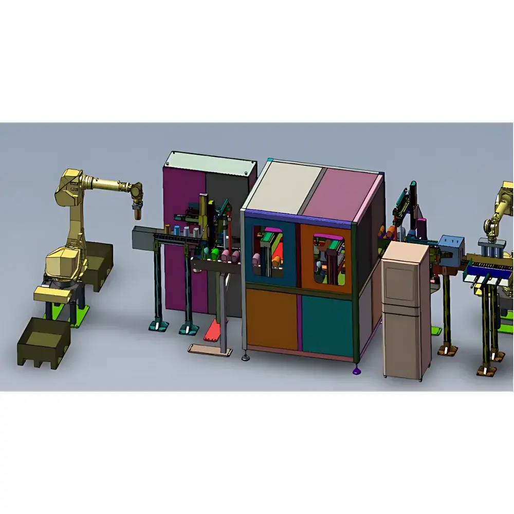
Olympus Custom Ultrasonic Testing System for Large Wind Turbine Roller Inspection
| Brand | Olympus |
|---|---|
| Origin | Shanghai, China |
| Manufacturer Type | Authorized Distributor |
| Product Origin | Domestic (China) |
| Model | Custom OEM System |
| Quotation | Upon Request |
| Application Field | Wind Power Component Quality Assurance |
| Channel Capacity | Up to 4 Channels |
| Inspection Method | Pulse-Echo Ultrasonic Testing with Equivalent Flaw Sizing (FBH Reference) |
| Minimum Detectable Flaw | 0.5 mm × 0.5 mm Flat-Bottom Hole (FBH) |
| Probe Compatibility | Conventional UT & Phased Array UT (PAUT) Probes |
| Automation Interface | Robotic Arm / Overhead Crane Integration with Machine Vision Guidance |
| Software Platform | Proprietary Real-Time UT Data Acquisition & Analysis Suite |
| Key Software Capabilities | Customizable UI, Zone-Based Defect Classification (Functional vs. Non-Functional Areas), Offline CAD-Based Path Planning, Automated Report Generation, Remote Supervisory Control, MES/ERP System Integration (OPC UA, REST API) |
Overview
The Olympus Custom Ultrasonic Testing System for Large Wind Turbine Roller Inspection is an engineered solution designed specifically for high-reliability non-destructive evaluation (NDE) of large-diameter cylindrical roller components used in wind turbine main shaft and pitch/yaw bearing assemblies. Built upon Olympus’ proven ultrasonic platform architecture and integrated with industry-specific automation and software logic, this system implements pulse-echo ultrasonic testing—compliant with ASTM E114, ISO 16810, and EN 1330-4—using either conventional single-element transducers or phased array ultrasonic testing (PAUT) probes. It delivers consistent detection sensitivity down to a 0.5 mm × 0.5 mm flat-bottom hole (FBH) equivalent reflector across curved surfaces with radii ranging from 150 mm to >1,200 mm. The system is deployed in final quality assurance lines where dimensional stability, microstructural integrity, and subsurface discontinuity control are critical to 20+ year service life requirements under variable-load cyclic fatigue conditions.
Key Features
- Multi-channel architecture supporting up to four independent ultrasonic acquisition channels—enabling simultaneous A-scan, B-scan, and sectorial S-scan data collection during rotational scanning.
- Integrated motion control interface compatible with industrial robotic arms (e.g., ABB, KUKA) and overhead gantry systems, synchronized with calibrated machine vision modules for precise part centering, orientation recognition, and automatic probe positioning.
- Fully proprietary software suite developed in-house, featuring real-time signal processing, adaptive gain compensation for curved surface coupling, and dynamic time-gain compensation (TGC) profile optimization per inspection zone.
- Zone-aware defect classification engine that differentiates between functional load-bearing zones (e.g., rolling contact bands) and non-functional transition or chamfer regions—applying distinct acceptance criteria per zone in accordance with ISO 28672 and wind industry-specific technical specifications (e.g., GL IEC 61400-22).
- Offline simulation module enabling import of STEP or IGES CAD models to generate collision-free ultrasonic scanning trajectories—including probe tilt angle, wedge delay calibration, and focal law configuration for PAUT inspections.
- Secure remote access capability via TLS-encrypted web interface, allowing off-site system monitoring, parameter adjustment, and diagnostic log retrieval without compromising local network integrity.
- Native connectivity to manufacturing execution systems (MES), enterprise resource planning (ERP), and quality management systems (QMS) through standardized protocols including OPC UA and RESTful APIs—supporting full traceability from raw material lot ID to final inspection certificate.
Sample Compatibility & Compliance
This system is validated for use with forged and heat-treated bearing steels (e.g., AISI 52100, 100Cr6, GCr15) and case-hardened alloys commonly employed in wind turbine roller manufacturing. It accommodates roller diameters from 200 mm to 1,800 mm and lengths up to 3,200 mm. All hardware and software components comply with CE marking requirements (2014/30/EU EMC Directive and 2014/35/EU LVD Directive). The software design follows ALCOA+ principles for data integrity and supports audit-ready electronic records compliant with FDA 21 CFR Part 11 and EU Annex 11 when deployed in regulated production environments. Calibration procedures align with ISO 17025-accredited laboratory practices and include documented traceability to NIST-traceable reference standards.
Software & Data Management
The embedded inspection software provides a unified graphical user interface (GUI) with modular layout configuration—allowing operators to define custom dashboards for live waveform display, C-scan mapping, depth profiling, and statistical process monitoring. All inspection data—including raw RF waveforms, processed A/B/C-scans, defect coordinates, sizing metrics (length, height, depth), and classification tags—are stored in a structured SQLite database with SHA-256 hashing for immutability verification. Audit trails record every operator action, parameter change, and report generation event with timestamp, user ID, and IP address. Export formats include PDF/A-2b inspection certificates, CSV for statistical analysis, and DICOM-RT for integration into centralized NDT data archives.
Applications
- Final inspection of large-diameter cylindrical rollers prior to bearing assembly in offshore and onshore wind turbine gearboxes and main bearings.
- In-process verification of heat treatment uniformity and absence of quench cracking or decarburization-related subsurface anomalies.
- Re-inspection of returned service components undergoing remanufacturing or life extension assessments.
- Supplier qualification audits requiring full digital inspection traceability and cross-system interoperability with Tier-1 OEM quality databases.
- Development and validation of new roller geometries and material grades under collaborative R&D programs with turbine manufacturers and steel producers.
FAQ
Does the system support both manual and automated operation modes?
Yes—operators can switch between fully automated robotic inspection, semi-automated guided scanning using teach-pendant interfaces, and manual probe manipulation with real-time feedback and measurement locking.
Can the software be validated for GMP/GLP compliance?
Yes—the software includes configurable electronic signature workflows, role-based access control (RBAC), and 21 CFR Part 11-compliant audit trail generation, making it suitable for deployment in ISO 13485-certified or GxP-aligned facilities.
What ultrasonic standards does the system adhere to?
It supports implementation of ASTM E114 (Standard Practice for Ultrasonic Testing of Materials), ISO 16810 (Non-destructive testing — Ultrasonic testing — General principles), and EN 1330-4 (Non-destructive testing — Terminology — Part 4: Terms used in ultrasonic testing), with configurable reporting templates aligned to customer-specific QA documentation requirements.
Is offline path planning compatible with third-party CAD platforms?
Yes—the system accepts STEP AP203/AP214, IGES, and Parasolid (.x_t) files; no proprietary CAD license is required for trajectory generation or simulation.
How is probe calibration managed across multiple inspection shifts?
Calibration status is tracked per probe ID with expiration dates, usage counters, and performance verification logs; automated alerts notify supervisors when recalibration is due based on cumulative scan hours or thermal drift thresholds.


