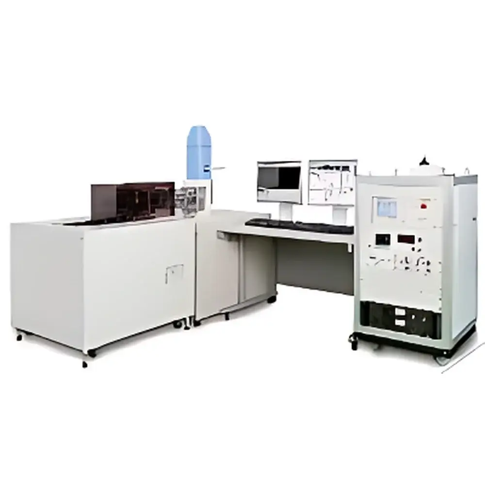
Shimadzu SEM-SERVO In-situ High-Temperature Fatigue Testing System with Integrated Scanning Electron Microscope
| Brand | Shimadzu |
|---|---|
| Origin | Japan |
| Manufacturer Type | Original Equipment Manufacturer (OEM) |
| Product Origin | Imported |
| Model | SEM-SERVO |
| Instrument Type | Electro-Hydraulic Servo Fatigue Testing System |
| Maximum Test Load | 10 kN |
| Frequency Range | 0.001–5 Hz (sine wave) |
| Operating Temperature Range | Ambient to +800 °C (optional high-temperature chamber) |
| SEM Resolution | 3 nm at 30 kV |
| SEM Magnification Range | ×5 to ×300,000 (digital display) |
| In-situ Observation Area | 6 mm × 16 mm (X-Y motorized stage) |
| Load-Triggered Static Imaging Capability | Optional (synchronized deformation freeze) |
Overview
The Shimadzu SEM-SERVO is an engineered in-situ high-temperature fatigue testing system that integrates a precision electro-hydraulic servo fatigue tester with a field-emission scanning electron microscope (FE-SEM) within a single, vibration-isolated platform. Unlike conventional post-mortem or ex-situ analysis workflows, this system enables real-time, load-synchronized microstructural observation during mechanical loading—capturing crack initiation, propagation, and microplasticity evolution under controlled thermal and mechanical boundary conditions. The core principle relies on synchronized actuation control and high-stability SEM imaging: the servo-controlled hydraulic actuator applies precisely defined cyclic loads (tension-compression, bending, or combined modes), while the integrated SEM acquires secondary electron (SE) and optional backscattered electron (BSE) images at designated intervals or triggered by load events. This coupling supports fundamental research into thermomechanical fatigue mechanisms, creep-fatigue interaction, and damage accumulation in advanced structural materials—including nickel-based superalloys, titanium alloys, ceramic matrix composites (CMCs), and metal-matrix composites (MMCs)—under service-relevant temperatures up to 800 °C.
Key Features
- Integrated dual-system architecture: Co-located fatigue tester and SEM share a common rigid base with active and passive vibration damping, minimizing relative drift (<0.5 µm RMS over 1 h at 10 kN, 1 Hz).
- High-temperature capability: Resistive coil heating module with closed-loop PID temperature control; validated uniformity ±3 °C across 5 mm × 5 mm gauge section at 800 °C.
- Multi-modal mechanical control: Closed-loop regulation of test force (±0.5% FS) and piston displacement (±0.2% FS); supports sine, triangle, ramp, and trapezoidal waveforms.
- Motorized X-Y specimen stage: 6 mm × 16 mm travel range with sub-micron repeatability; compatible with standard SEM stubs and custom high-temperature holders.
- Vacuum-compatible load train: Force transducer equipped with vacuum suction compensation mechanism to eliminate parasitic bending moments during in-vacuum testing.
- Load-synchronized static imaging option: Triggered acquisition freezes SEM frame at peak load or zero-crossing points, eliminating motion blur during dynamic cycling (requires optional pulse synchronization module).
Sample Compatibility & Compliance
The SEM-SERVO accommodates standard ASTM E466-compliant dog-bone tensile specimens (e.g., 2 mm gauge width, 0.5 mm thickness), as well as custom geometries for bend or compact tension (CT) configurations. All high-temperature fixtures are fabricated from molybdenum or tungsten alloys to maintain dimensional stability and oxidation resistance. The system complies with ISO 12106 (metallic materials — fatigue testing — axial strain-controlled method), ASTM E606 (strain-controlled fatigue testing), and ASTM E2007 (high-temperature mechanical testing). For regulated environments, optional audit-trail logging and user-access controls support GLP/GMP documentation requirements per 21 CFR Part 11 when paired with Shimadzu’s TruLab™ software suite.
Software & Data Management
Control and acquisition are unified via Shimadzu’s proprietary TruLab™ Fatigue-SEM Platform—a Windows-based application supporting simultaneous waveform definition, thermal ramp programming, and SEM parameter scripting. All test data—including load, displacement, temperature, and timestamped image metadata—are stored in HDF5 format with embedded calibration certificates and operator annotations. Batch export to MATLAB, Python (via h5py), or commercial FEA preprocessors (e.g., ANSYS Workbench, Thermo-Calc) is natively supported. Image datasets include EXIF-like headers containing exact load phase angle, cycle count, and thermal gradient maps derived from integrated thermocouple arrays.
Applications
- Quantitative in-situ characterization of fatigue crack growth thresholds (da/dN vs. ΔK) under isothermal and thermomechanical cycling.
- Microstructure-sensitive fatigue modeling: Correlating local grain orientation (EBSD-ready), precipitate distribution, and slip band formation with macroscopic hysteresis loops.
- Oxidation-assisted cracking studies in turbine disk alloys exposed to 600–800 °C air environments.
- Interface debonding kinetics in fiber-reinforced composites under cyclic shear loading.
- Validation of crystal plasticity finite element (CPFE) simulations using experimentally resolved dislocation pile-ups and twin boundary migration.
FAQ
Can the SEM operate independently of the fatigue tester?
Yes—the SEM column and detector subsystems retain full standalone functionality for routine surface morphology or compositional analysis outside mechanical testing protocols.
What vacuum level is maintained during high-temperature testing?
The chamber achieves ≤1 × 10⁻⁴ Pa during static imaging; pressure rises to ≤5 × 10⁻³ Pa under active heating at 800 °C, fully compatible with tungsten-filament and CeB₆ electron sources.
Is third-party SEM integration supported?
No—the system is designed exclusively for Shimadzu’s proprietary SEM optics and signal synchronization architecture; retrofitting non-Shimadzu columns voids mechanical and thermal warranty coverage.
How is thermal drift compensated during long-duration tests?
Real-time stage position correction is applied using a laser interferometer feedback loop (optional upgrade), reducing thermal drift to <100 nm/h at 800 °C.
Are ASTM/ISO-compliant test reports auto-generated?
TruLab™ includes configurable report templates aligned with ASTM E466 Annex A1 and ISO 12106 Clause 9, with digital signatures and revision-controlled PDF export.


