YANRUN HMAS-HT1300CM Full-Temperature-Field High-Temperature Vickers Hardness Tester (up to 1200°C)
| Brand | YANRUN |
|---|---|
| Origin | Shanghai, China |
| Manufacturer Type | Direct Manufacturer |
| Instrument Type | Vickers Hardness Tester |
| Load Range | 0.1–30 kgf (standard), up to 150 kgf (optional) |
| Temperature Range | 200–1200°C |
| Temperature Uniformity | ≤ ±5°C across 100×80×80 mm furnace chamber |
| Thermal Control Accuracy | ±1°C |
| Heating Element | Silicon Carbide Rods |
| Thermocouple | Type S Platinum-Rhodium |
| Objective Working Temp | ≤1200°C (10× or 20× high-temp objective) |
| Optical Magnification | 1000× (standard), 2000× (optional) |
| Objective Resolution | 1.44 µm (10×), 1.19 µm (20×) |
| Loading Modes | Constant Load / Constant Rate |
| Load Resolution | 0.01% FS |
| Hold Time | Up to 72 h |
| Multi-Axis Motion Control | Up to 9 axes, positioning accuracy ≤ ±1 µm |
| Sample Exchange Time (in-situ) | ≤50 s at 1200°C |
| Cooling Options | Circulating air (≤5 s cooldown), optional water/gas cooling modules |
| Compliance | Designed for GLP/GMP-aligned materials R&D environments |
Overview
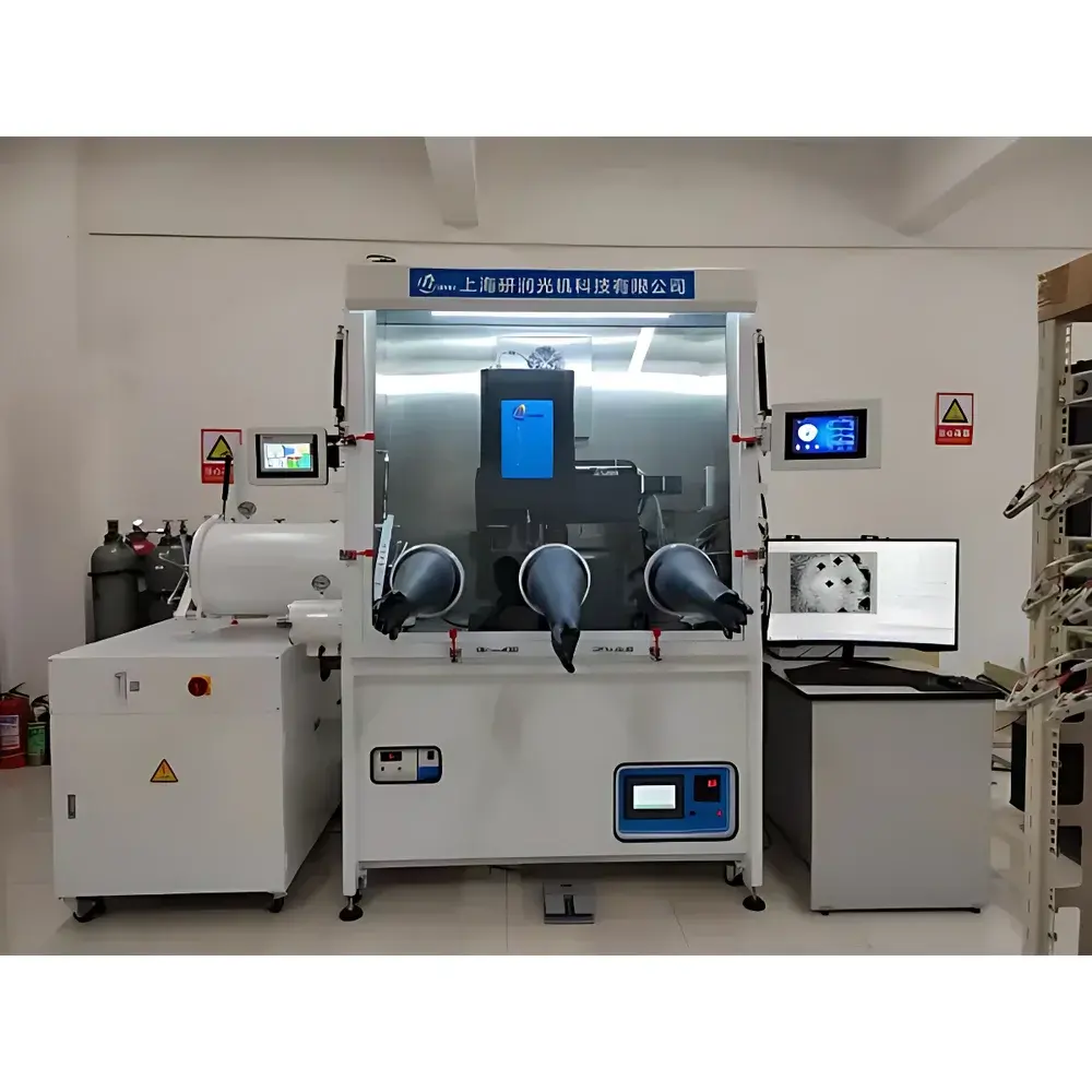
The YANRUN HMAS-HT1300CM is a full-temperature-field high-temperature Vickers hardness tester engineered for in-situ mechanical property evaluation of advanced materials under controlled thermal conditions from 200°C to 1200°C. Unlike conventional hot-stage microhardness systems that isolate heating and indentation, the HMAS-HT1300CM maintains a uniform, stable temperature field across the entire measurement zone—including the indenter, optical path, load train, and sample—enabling true real-time indentation mechanics analysis at elevated temperatures. Its core architecture integrates a high-stability silicon carbide furnace with S-type platinum-rhodium thermocouple feedback, precision multi-axis ceramic-compatible motion stages, and a purpose-built high-temperature optical train featuring 10× and optionally 20× objectives rated for continuous operation at 1200°C. This enables direct observation of indentation plasticity, crack initiation, creep deformation, and thermal recovery phenomena without thermal lag or positional drift—critical for studying superalloys, refractory ceramics, CMCs, and nuclear fuel cladding materials.
Key Features
- Full-temperature-field design ensures simultaneous thermal equilibration of sample, indenter, optics, and load sensor—eliminating thermal gradient artifacts during indentation.
- Dynamic load control system with 0.1–30 kgf standard range (extendable to 150 kgf); load resolution of 0.01% full scale; accuracy ±2% ≤1 kgf, ±0.5% >1 kgf.
- In-situ high-resolution imaging: 1000× total magnification (10× objective + 100× eyepiece equivalent); 1.44 µm lateral resolution; optional 20× objective for enhanced feature discrimination.
- Multi-axis synchronized motion control (up to 9 axes) with ≤±1 µm repeatability and ≤0.1 µm step resolution—enabling precise Z-height compensation, XY stage navigation, and automated multi-point grid testing within the same thermal field.
- High-throughput in-situ sample exchange: manual or motorized rapid-change mechanism completes specimen swap in ≤50 seconds at 1200°C—preserving thermal stability and minimizing experimental downtime.
- Extended hold capability: programmable dwell times from 1 second to 72 hours at constant load, supporting long-term creep, stress relaxation, and thermal aging studies.
- Real-time force–time data acquisition: continuous sampling during loading, holding, and unloading phases—facilitating construction of viscoplastic constitutive models and indentation size effect (ISE) analysis.
- Modular environmental integration: compatible with inert-gas gloveboxes (H₂O/O₂ ≤1 ppm), circulating air/gas cooling (≤5 s cooldown), and optional water-cooling for auxiliary electronics and furnace jackets.
Sample Compatibility & Compliance
The HMAS-HT1300CM accommodates cylindrical specimens up to φ30 × 30 mm and supports custom fixtures for irregular geometries. It is routinely deployed for testing nickel-based superalloys (e.g., Inconel 718, Haynes 230), silicon carbide composites, tungsten heavy alloys, and oxide dispersion strengthened (ODS) steels. All hardware components—including the pyramidal diamond indenter, ceramic guide bushings, and high-temp lens mounts—are qualified for continuous exposure at 1200°C. The system complies with the dimensional and procedural requirements of ASTM E384 (Standard Test Method for Microindentation Hardness of Materials), ISO 6507-1 (Metallic Materials — Vickers Hardness Test), and USP (Instrument Qualification of Mechanical Testing Systems). Data acquisition and instrument control logs support audit-ready electronic records aligned with FDA 21 CFR Part 11 principles, including user authentication, change tracking, and immutable timestamping—making it suitable for regulated R&D environments operating under GLP or GMP frameworks.
Software & Data Management
The integrated control software provides unified management of thermal ramping, load profiling, stage motion, image capture, and real-time force–time plotting. Each test generates a timestamped .csv dataset containing synchronized temperature, load, displacement, time, and coordinate metadata. Image-based indentation analysis includes automatic detection of diagonal lengths, crack length quantification, and phase-contrast-enhanced surface topography mapping. Custom scripting (Python API) allows integration with third-party modeling tools for inverse FEM fitting, hardness–temperature correlation modeling, and machine learning–assisted defect classification. Audit trails record all parameter modifications, operator logins, calibration events, and firmware updates—retained for ≥10 years per configurable retention policy. Export formats include ASTM E1445-compliant XML reports and NIST-traceable calibration certificates.
Applications
- High-temperature creep resistance characterization of turbine blade alloys under simulated service conditions.
- In-situ fracture toughness evaluation via indentation-induced cracking at elevated temperatures—correlating KIC with thermal activation energy.
- Thermal aging effects on hardness evolution in zirconium alloy fuel cladding exposed to PWR/BWR coolant environments.
- Interfacial strength assessment in metal–ceramic brazed joints via localized indentation at bonding interfaces.
- Creep–fatigue interaction studies using cyclic indentation protocols with variable dwell intervals and thermal cycling ramps.
- Validation of thermomechanical finite element models through direct comparison of predicted vs. measured indentation depth–load curves.
- Development of temperature-dependent hardness standards for reference materials used in aerospace and nuclear QA/QC laboratories.
FAQ
What is the maximum continuous operating temperature of the optical system?
The 10× and 20× objectives are certified for uninterrupted operation at ≤1200°C for up to 50 hours per cycle.
Can the system perform hardness testing under vacuum or inert atmosphere?
Yes—the base configuration integrates with optional gloveboxes or vacuum transition chambers; inert gas purging (Ar, N₂) is standard, with O₂/H₂O levels maintained below 1 ppm.
Is force calibration traceable to national standards?
All load cells are factory-calibrated against NIST-traceable deadweight standards; on-site recalibration kits and procedures are provided per ISO/IEC 17025 guidelines.
How is thermal drift compensated during long-duration hold tests?
A closed-loop Z-axis thermal expansion compensator actively adjusts sample height in real time using dual high-temp LVDTs and PID-controlled piezoelectric actuators.
Does the system support automated multi-point hardness mapping across a temperature gradient?
Yes—programmable thermal ramping combined with XY stage automation enables spatially resolved hardness profiling across defined temperature gradients (e.g., 800°C → 1100°C linear ramp over 50 mm).


