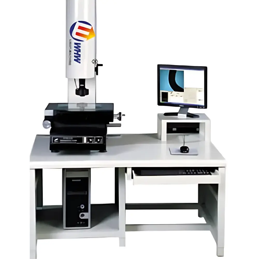
YANRUN YR-F2010 Practical Image Measuring System
| Brand | YANRUN |
|---|---|
| Origin | Shanghai, China |
| Manufacturer Type | Direct Manufacturer |
| Country of Origin | China |
| Model | YR-F2010 |
| Price | USD 1 (Base Quotation Reference Only) |
| Table Surface (Metal) | 404 × 228 mm |
| Glass Stage Size | 260 × 160 mm |
| Travel Range (X×Y) | 200 × 100 mm |
| Overall Dimensions | 600 × 550 × 920 mm |
| Z-Axis Vertical Travel | 175 mm |
| Digital Readout Resolution (X/Y/Z) | 0.0005 mm |
| Positioning Accuracy (X/Y) | ≤ (3 + L/200) µm |
| Imaging System | Sony Color CCD Camera |
| Objective Lens Magnification | 0.7×–4.5× (Dual-Focus) |
| Total Video Magnification | 28×–180× |
| Illumination | Adjustable LED Surface & Transmission Light Sources |
| Power Supply | 220 V ±10%, 50 Hz |
| Operating Environment | 20 °C ±3 °C, 45–75% RH |
| Standard Software | Auto-Edge Detection, Deburring, Geometric Feature Measurement (Points, Lines, Circles, Circle-to-Circle Distance, Part Alignment), Stage Load Capacity: ≥300 kg (for YR-F2010-compatible base platform, 1120 × 730 × 780 mm) |
Overview
The YANRUN YR-F2010 Practical Image Measuring System is a benchtop optical coordinate measuring instrument engineered for precision geometric metrology in quality control laboratories, toolrooms, and R&D environments. It operates on the principle of high-resolution video microscopy combined with motorized stage positioning and calibrated image-based dimensional analysis. The system captures magnified images of parts placed on a rigid granite or metal base platform, then uses pixel-to-length calibration and sub-pixel edge detection algorithms to determine geometric features—including point coordinates, line orientation, circle diameter, concentricity, parallelism, and perpendicularity—with traceable repeatability. Designed for ISO/IEC 17025-aligned workflows, the YR-F2010 delivers consistent measurement uncertainty performance under controlled environmental conditions (20 °C ±3 °C, 45–75% RH), making it suitable for first-article inspection, incoming material verification, and in-process dimensional validation across mechanical, automotive, and precision machining sectors.
Key Features
- Stable mechanical architecture featuring a 404 mm × 228 mm metal worktable and 260 mm × 160 mm optical glass stage for high-transparency transmission measurement of transparent or translucent components.
- Precision linear motion system with 200 mm (X) × 100 mm (Y) travel range and 175 mm vertical Z-axis lift—enabling multi-angle focusing and layered feature assessment.
- Dual-focus telecentric objective lens (0.7×–4.5×) paired with a Sony progressive-scan color CCD sensor, delivering real-time video magnification from 28× to 180× with minimal distortion and high contrast resolution.
- Independent LED surface and transmitted illumination modules, each with continuous brightness control—supporting both silhouette-based contour analysis and surface-feature contrast enhancement.
- Digital encoder feedback on all axes with 0.5 µm resolution, compliant with ISO 10360-7 for coordinate measuring machine (CMM) performance verification.
- Integrated thermal-compensated granite base design (compatible with optional 1120 mm × 730 mm × 780 mm load-rated platform supporting ≥300 kg static capacity) to minimize vibration-induced measurement drift.
Sample Compatibility & Compliance
The YR-F2010 accommodates a broad range of manufactured parts—from small stamped components and PCBs to machined housings and injection-molded plastic assemblies—provided they fit within the 200 mm × 100 mm measurement envelope and remain stable during imaging. Its non-contact measurement methodology eliminates part deformation risks associated with tactile probing. The system supports ASTM E29, ISO 1101 (Geometrical Product Specifications), and ISO 14253-1 (Decision rules for proving conformity or nonconformity) through documented measurement uncertainty estimation and traceable calibration procedures. While not certified to FDA 21 CFR Part 11 out-of-the-box, its software architecture permits audit-trail configuration and electronic signature integration when deployed under validated GLP/GMP frameworks.
Software & Data Management
The standard measurement software provides automated edge detection with adaptive thresholding, real-time deburring filters, and geometric fitting routines compliant with least-squares and minimum-zone evaluation methods per ISO 1101. Users can define custom measurement sequences, generate GD&T-compliant reports (including true position, circularity, and profile tolerances), and export results in CSV, PDF, or XML formats. All measurement data—including raw image frames, coordinate sets, operator ID, timestamp, and environmental logs—is stored with immutable metadata. Optional database connectors support integration with MES or QMS platforms via ODBC or RESTful API endpoints.
Applications
- Dimensional verification of micro-gears, watch components, and medical device housings requiring sub-10 µm tolerance compliance.
- PCB solder paste inspection and pad alignment validation prior to SMT assembly.
- Tooling and die inspection—including electrode wear analysis and cavity depth profiling using focus-stacking techniques.
- Plastic part warpage assessment via multi-point flatness mapping across molded surfaces.
- Educational use in metrology training labs for teaching coordinate geometry, image processing fundamentals, and uncertainty budgeting principles.
FAQ
What is the maximum part height that can be accommodated under the lens?
The Z-axis vertical travel of 175 mm allows clearance for parts up to approximately 150 mm in height when using standard lens configurations—subject to field-of-view constraints at higher magnifications.
Is calibration certification included with delivery?
A factory calibration report (traceable to national standards) is provided; however, end-user ISO/IEC 17025 accreditation requires on-site verification by an accredited metrology laboratory.
Can the system measure threaded features or screw pitch?
Yes—when combined with appropriate lighting and edge-enhancement filters, the YR-F2010 can resolve thread profiles and calculate pitch, major/minor diameters, and flank angles for M2–M12 fasteners.
Does the software support multi-language UI and report generation?
The interface defaults to English; localized language packs (including German, French, and Japanese) are available upon request for regulated environments.
What maintenance intervals are recommended for long-term accuracy retention?
Biannual verification of stage linearity, lens calibration, and illumination uniformity is advised; annual recalibration of the entire system is recommended for ISO-compliant operations.