YANRUN YRMAT2515B Dual-Axis Electronic Autocollimator (0.5 arcsec Resolution)
| Brand | YANRUN |
|---|---|
| Origin | Shanghai, China |
| Manufacturer Type | OEM Manufacturer |
| Country of Origin | China |
| Model | YRMAT2515B |
| Price | USD 5,600 (FOB Shanghai) |
| Focal Length | 200 mm |
| Aperture | 38 mm |
| Light Source | High-Stability Semiconductor LED |
| Measurement Range | 0–15 m |
| Detector | High-Resolution CMOS Position-Sensitive Sensor |
| Angular Resolution | Adjustable from 1.0 to 0.1 arcsec |
| Field of View (X/Y) | 2600″ × 2000″ |
| Accuracy (Center) | ±0.5 arcsec (within ±100″ range), ±1.0 arcsec (within ±1000″ range) |
| Interface | USB 2.0/3.0 |
| OS Requirement | Windows 7/10/11 (64-bit), Intel Core i3-4th Gen or higher, ≥2.3 GHz, ≥4 GB RAM |
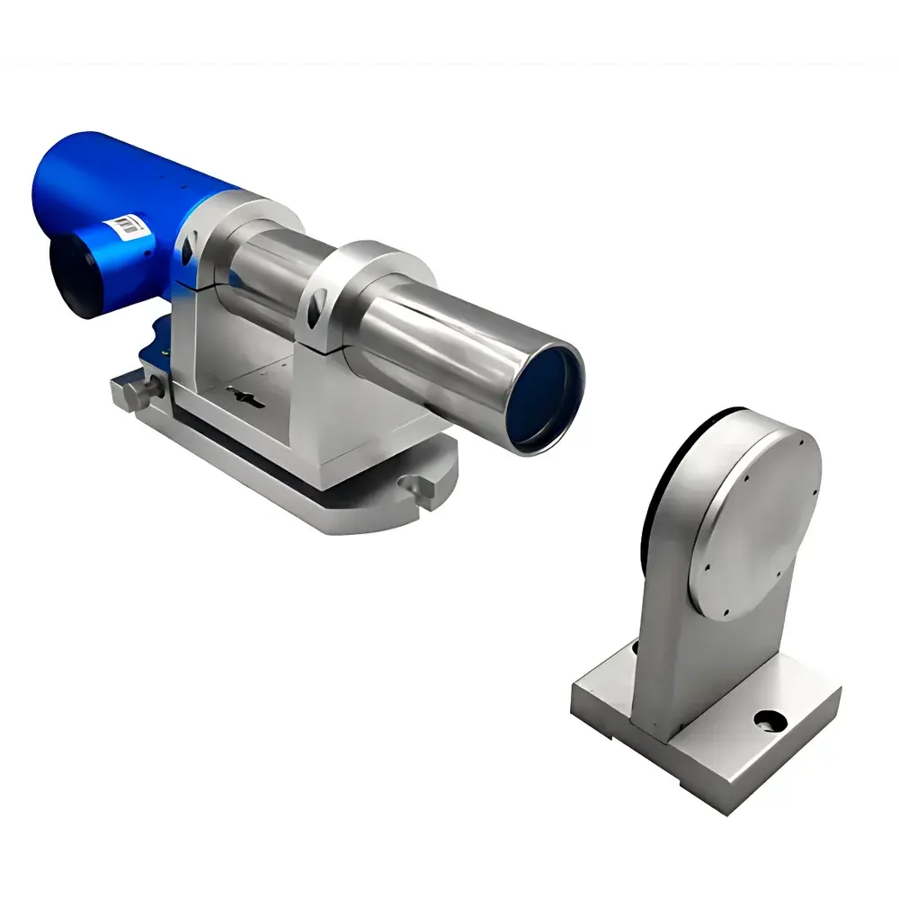
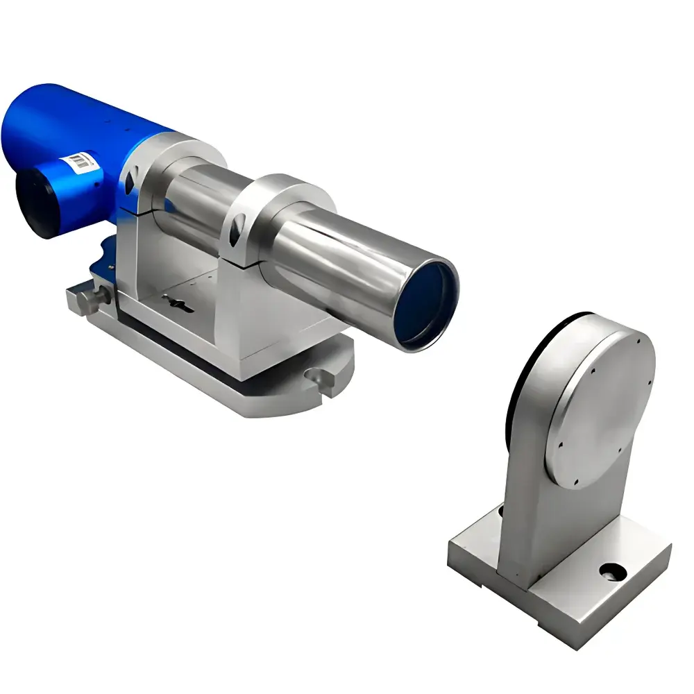
| Dimensions | 388 × 135 × 125 mm |
| Weight | 3.6 kg |
Overview
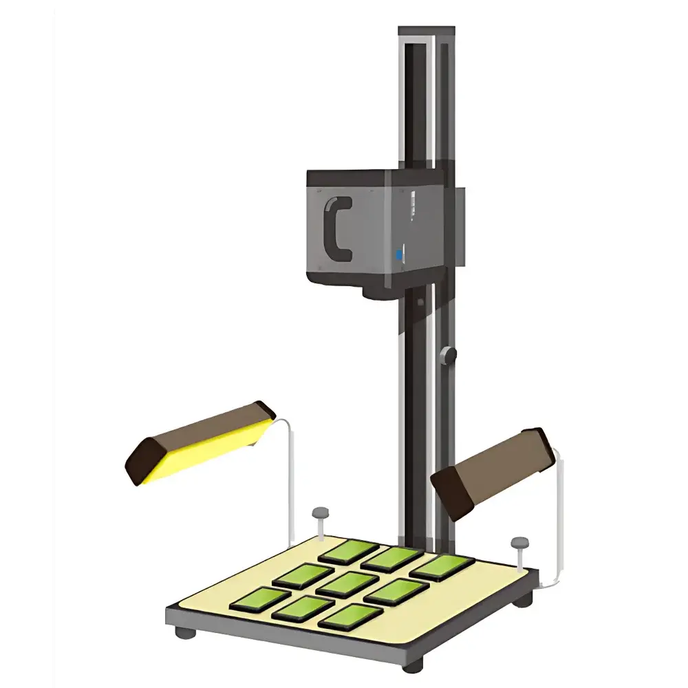
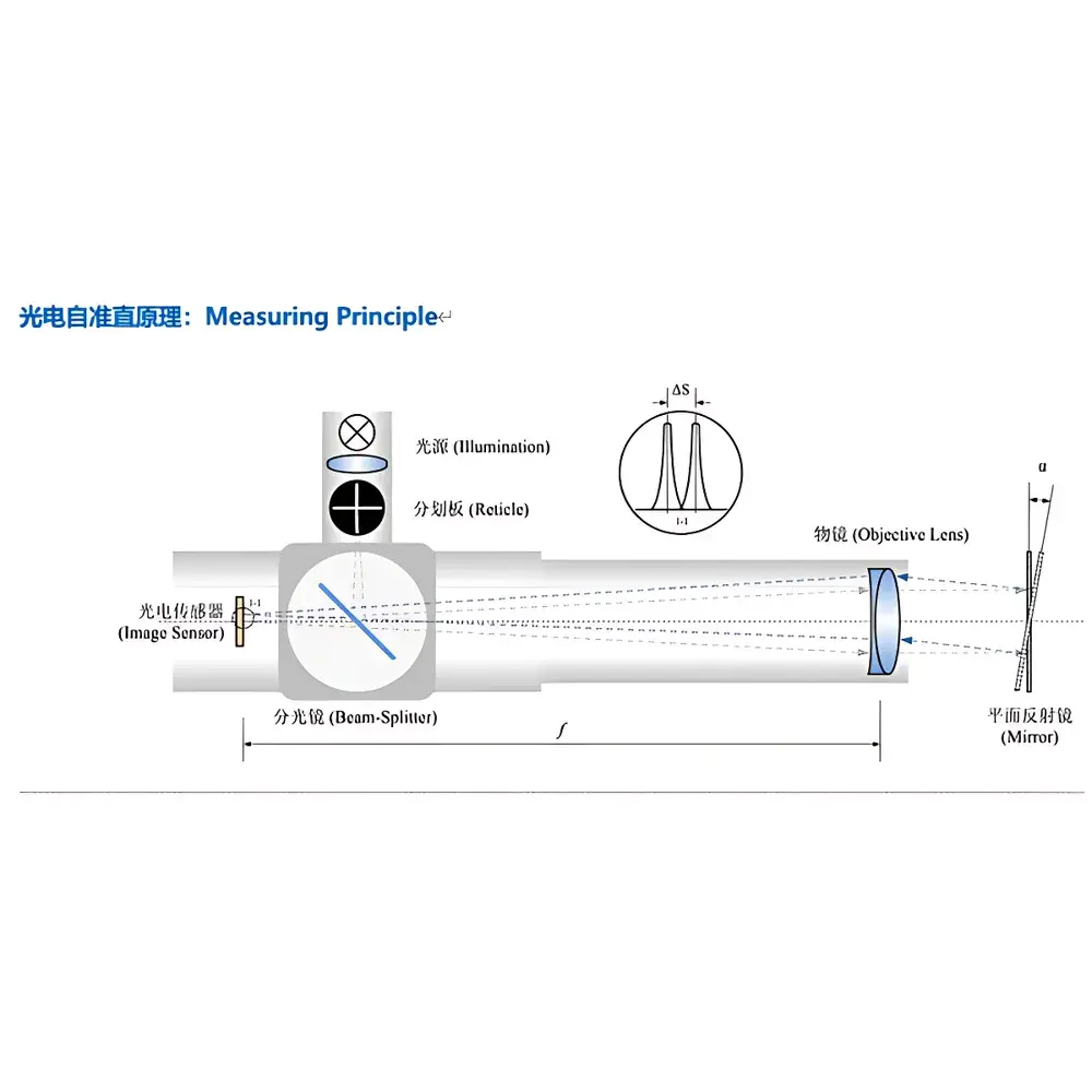
The YANRUN YRMAT2515B is a dual-axis electronic autocollimator engineered for high-precision angular metrology in industrial metrology labs, optical assembly facilities, and precision mechanical manufacturing environments. It operates on the fundamental principle of optical autocollimation: a collimated beam—generated by projecting a reticle located at the focal plane of a 200 mm focal length objective lens—is reflected off a planar mirror and reimaged onto a high-stability CMOS position-sensitive detector located at the same focal plane. When the mirror rotates by an angle α, the returned image shifts by ΔS ≈ 2f·α (where f = 200 mm), enabling sub-arcsecond angular displacement quantification via pixel-level centroid detection. Unlike traditional visual autocollimators requiring subjective eyepiece alignment, the YRMAT2515B eliminates observer-dependent error through real-time digital imaging and automated centroid calculation. Its compact, benchtop-integrated architecture supports traceable calibration under ISO/IEC 17025-compliant conditions and meets functional requirements aligned with ASTM E2917 (Standard Practice for Measuring Angular Displacement) and ISO 230-1 (Machine Tool Testing — Part 1: Geometric Accuracy).
Key Features
- Dual-axis simultaneous measurement (X and Y) with independent resolution adjustment (0.1–1.0 arcsec), enabling full 2D angular deviation mapping without mechanical reorientation.
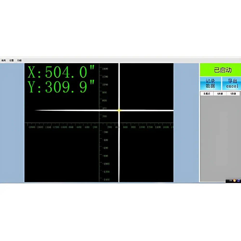
- Real-time electronic eyepiece display with live centroid tracking, supporting dynamic alignment verification during optical component adjustment or machine tool commissioning.
- High-stability semiconductor LED illumination system (rated lifetime >50,000 hours), eliminating thermal drift and intensity fluctuation common in halogen or laser sources.
- Integrated two-axis adjustable base with fine-thread micrometers (±5° tilt range, 1 µrad repeatability), ensuring stable mounting on granite tables, optical breadboards, or CNC machine beds.
- USB 2.0/3.0 interface with deterministic latency (<15 ms frame-to-host transfer), compatible with Windows 7–11 (64-bit) and validated for use in GLP/GMP-regulated environments requiring audit-trail-capable software logging.
- Modular firmware architecture permitting field-upgradable measurement algorithms—including least-squares best-fit line, harmonic error decomposition, and multi-point reference averaging—for enhanced uncertainty reduction in repetitive measurements.
Sample Compatibility & Compliance
The YRMAT2515B is designed for use with standard optical flat mirrors (λ/20 surface accuracy, 25–50 mm diameter), retroreflective targets, and custom-mounted prisms. It complies with electromagnetic compatibility standards EN 61326-1 (industrial environment) and safety standard EN 61010-1. While not certified to FDA 21 CFR Part 11 out-of-the-box, its control software supports optional configuration for electronic signature, user access levels, and immutable audit trails—enabling validation in regulated QC/QA workflows. Calibration certificates are issued per ISO/IEC 17025-accredited laboratories upon request; recommended recalibration interval is 12 months under controlled lab conditions (20 ± 0.5 °C, <40% RH, vibration-isolated platform). For metrological traceability, the instrument’s angular scale is referenced to NIST-traceable interferometric angle standards.
Software & Data Management
The bundled YRMAT Control Suite runs natively on Windows platforms and provides real-time visualization of crosshair displacement vectors, statistical process control (SPC) overlays, and time-series trending. All raw sensor data (centroid coordinates, timestamp, temperature reading from internal sensor) are stored in binary .yrm format with embedded metadata (operator ID, project tag, environmental log). Export options include CSV, XLSX (with automatic generation of ISO 1101-compliant GD&T reports), and PDF summary documents containing measurement uncertainty budgets per GUM (Guide to the Expression of Uncertainty in Measurement). Optional modules include Straightness Analysis (per ISO 230-2), Planarity Reconstruction (via grid-based bridge plate scanning), and Rotary Table Calibration (synchronizing with encoder signals via TTL trigger input). Software updates are delivered via secure HTTPS portal with SHA-256 integrity verification.
Applications
- Precision alignment of optical benches, laser cavities, and interferometer arms in R&D photonics labs.
- Geometric error mapping of linear motion stages—including straightness, pitch, yaw, and roll deviations—across 15 m travel ranges.
- Verification of angular repeatability and positioning accuracy of air-bearing rotary tables used in semiconductor lithography equipment.
- In-process monitoring of mirror tilt stability in space-borne telescope secondary mirror actuators (validated per ECSS-E-ST-70-01C).
- Calibration of polygon mirrors and multi-facet angle standards (8-, 12-, 24-face) in national metrology institutes.
- GD&T evaluation of machined components per ASME Y14.5—specifically angularity, perpendicularity, parallelism, and flatness derived from sequential angular scans.
FAQ
What is the minimum measurable angle and how is resolution adjusted?
The YRMAT2515B achieves a base resolution of 0.1 arcsec through pixel binning and centroid interpolation algorithms; resolution is selectable in software (0.1 / 0.2 / 0.3 / 0.5 / 1.0 arcsec) depending on required speed vs. noise trade-off.
Does the system require warm-up before high-accuracy measurement?
Yes—optimal angular stability is achieved after ≥15 minutes of continuous operation; for metrological-grade results (e.g., calibration lab use), thermal equilibration on a temperature-stabilized surface for ≥24 hours is recommended prior to formal verification.
Can the instrument measure over 15 meters?
The specified 0–15 m range assumes use with a standard 25 mm aperture mirror under ambient lighting; extended range (up to 30 m) is feasible using larger-diameter reflectors and low-noise acquisition modes, though angular uncertainty increases proportionally with distance due to beam divergence and atmospheric turbulence.
Is third-party software integration supported?
Yes—DLL and LabVIEW-compatible API libraries are provided for custom automation; Python bindings (via ctypes) and MATLAB instrument control toolbox support are available upon request.
How is traceability maintained during field use?
Each unit ships with a factory calibration report referencing NIST-traceable angle artifacts; users may perform intermediate verification using the included reference mirror and documented zero-shift procedure, with results logged automatically in the audit trail.