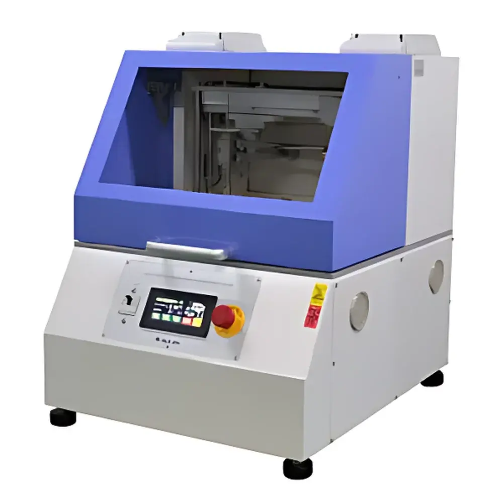
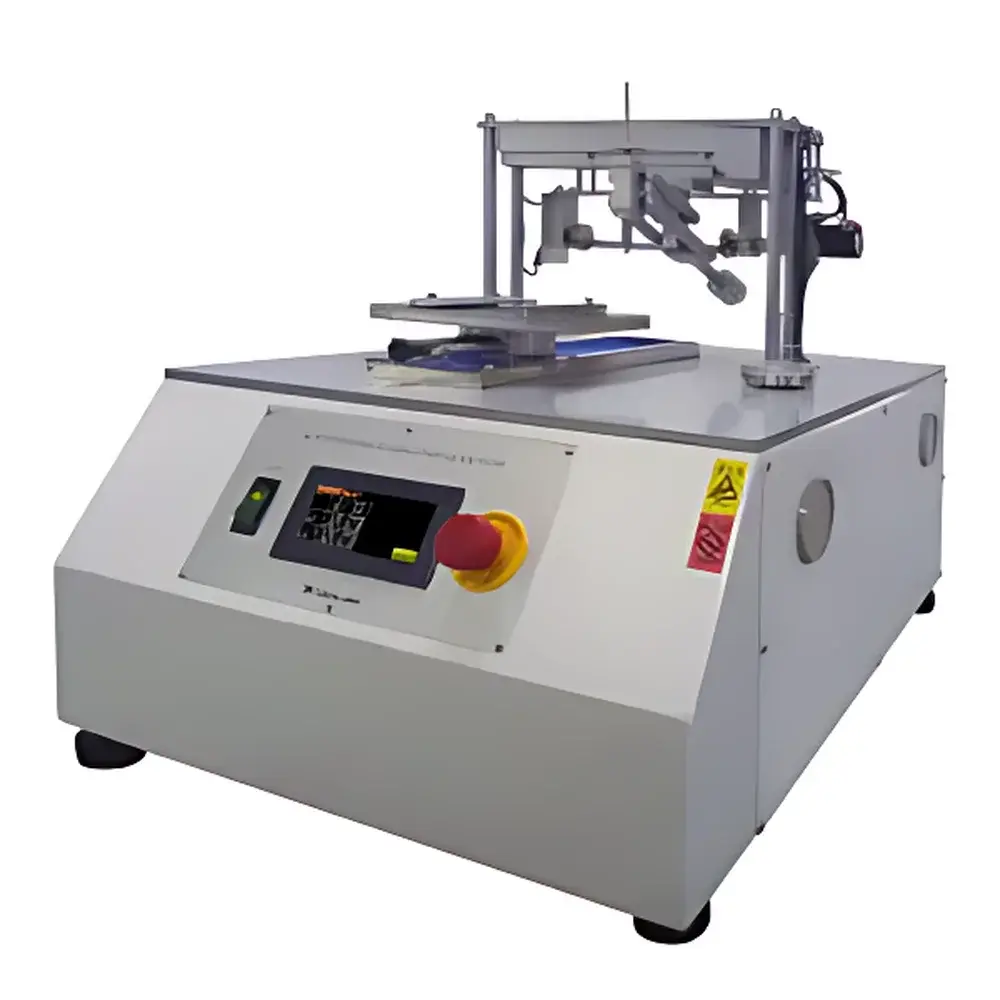
Yasuda No.551-AUTO-1 Automatic Cross-Cut Adhesion Tester
| Brand | Yasuda |
|---|---|
| Origin | Japan |
| Model | No.551-AUTO-1 |
| Test Standards | JIS D 0202, JIS K 5400, JIS K 5600-5-6, ASTM D2197, ISO 2409 |
| Sample Stage | 90 × 90 mm, 90° automatic rotation |
| Max. Travel | 50 mm (X), 50 mm (Y) |
| Cut Spacing | 0.5 / 1.0 / 1.5 / 2.0 mm (4-step selection) |
| Cutting Speed | 5 / 10 / 15 / 20 mm/s |
| Number of Cuts | Programmable via timer (standard: 6 or 11 cuts) |
| Load Range | 10–350 gf (counterweight-based) |
| Cutting Needle | φ3 mm diameter, 23 mm length, 60° tip angle |
| Power Supply | AC 100 V, 1-phase, 5 A, 50/60 Hz |
| Dimensions (w/o guard) | 630 × 750 × 700 mm |
| Weight | ~90 kg |
| Dimensions (with guard) | 630 × 750 × 760 mm |
| Weight | ~95 kg |
| Optional Accessories | Electrical continuity module, blade mounting jig, linear displacement sensor |
Overview
The Yasuda No.551-AUTO-1 Automatic Cross-Cut Adhesion Tester is a precision-engineered instrument designed for objective, repeatable evaluation of coating adhesion to rigid substrates using the standardized cross-cut method. It operates on the principle of controlled mechanical incision: a hardened steel needle traverses the coated surface in orthogonal directions under precisely regulated load and geometry, generating a grid of parallel cuts that penetrate through the film to the substrate. The resulting lattice pattern enables quantitative assessment of delamination resistance—either visually against standardized rating scales (e.g., ISO 2409’s 0–5 classification) or in conjunction with adhesive tape lift tests per ASTM D3359. Unlike manual tools subject to operator variability in pressure, angle, and speed, the No.551-AUTO-1 ensures strict compliance with test parameters defined in JIS D 0202, JIS K 5400, JIS K 5600-5-6, ASTM D2197, and ISO 2409. Its fully automated motion control eliminates human-induced inconsistencies, making it suitable for quality control laboratories operating under GLP or IATF 16949 frameworks where traceability and inter-laboratory reproducibility are mandatory.
Key Features
- Programmable bidirectional cutting stage with independent X/Y axis control (max. 50 mm travel each), enabling precise grid formation on 90 × 90 mm specimens;
- Four-step selectable cut spacing (0.5, 1.0, 1.5, 2.0 mm) and four discrete cutting speeds (5–20 mm/s), allowing method adaptation across diverse coating thicknesses and substrate hardnesses;
- Counterweight-based loading system offering continuous adjustment from 10 gf to 350 gf, calibrated to meet force tolerance requirements specified in ISO 2409 Annex A;
- Fixed-geometry cutting needle (φ3 mm shank, 23 mm overall length, 60° conical tip) manufactured to JIS B 0601 surface finish standards for consistent edge sharpness and wear resistance;
- Motorized 90° specimen rotation mechanism ensuring perpendicular alignment between successive cut passes without manual repositioning;
- Integrated safety enclosure compliant with IEC 61000-6-2 EMC immunity and ISO 13857 access protection guidelines (optional configuration);
- Modular design supporting factory-installed options including electrical continuity verification (for conductive coatings), precision blade alignment jigs, and linear displacement sensors for real-time stroke monitoring.
Sample Compatibility & Compliance
The No.551-AUTO-1 accommodates flat, rigid panels up to 90 × 90 mm, including cold-rolled steel, aluminum alloy, glass, and polymer sheets meeting ASTM D609 substrate preparation criteria. It supports coatings ranging from thin automotive clearcoats (150 µm), provided substrate rigidity prevents flexure during cutting. All operational parameters—including load application rate, dwell time post-incision, and environmental conditioning prior to testing—align with ISO 2409:2013 clause 6 (test conditions) and ASTM D2197 section 7 (procedure). The instrument’s mechanical repeatability (±1.2% RSD in cut depth across 20 replicates at 200 gf, verified per ISO 5725-2) satisfies internal audit requirements for QC labs certified to ISO/IEC 17025:2017.
Software & Data Management
While the No.551-AUTO-1 operates as a standalone electromechanical tester without embedded microprocessor control, its analog-digital hybrid architecture includes TTL-level trigger outputs and analog voltage signals (0–10 V) synchronized to cut initiation, stage position, and load activation. These interfaces enable integration with third-party data acquisition systems (e.g., National Instruments DAQmx platforms) for timestamped logging of operational events. When paired with optional continuity modules, binary pass/fail signals can be routed to LIMS environments supporting 21 CFR Part 11-compliant electronic records. Calibration certificates—traceable to NMIJ (National Metrology Institute of Japan) force and displacement standards—are supplied with each unit and include uncertainty budgets per GUM (JCGM 100:2008).
Applications
- Automotive OEM and Tier-1 suppliers validating paint adhesion on body panels per JIS D 0202 and GMW 14872;
- Aerospace component manufacturers assessing primer-to-aluminum bond integrity under MIL-PRF-85285;
- Coating formulators conducting DOE studies on resin crosslink density vs. adhesion performance;
- Electroplating facilities verifying nickel-chromium layer cohesion on ABS plastic substrates;
- Research institutions performing accelerated weathering correlation studies (e.g., QUV + cross-cut) per ISO 11341.
FAQ
Does the No.551-AUTO-1 comply with FDA-regulated coating validation protocols?
No—while it meets ISO/IEC 17025 metrological requirements, it is not validated for pharmaceutical primary packaging applications governed by USP or . Its use is restricted to industrial and automotive sectors.
Can cutting parameters be saved as reusable test methods?
Not natively—the unit lacks onboard memory. However, external PLCs or LabVIEW scripts can store and recall parameter sets via its analog/digital I/O interface.
What maintenance intervals are recommended for the cutting needle?
Yasuda specifies replacement after 500 full-grid cycles or upon measurable tip radius deviation >±5 µm (verified via profilometry), whichever occurs first.
Is calibration required before each test series?
Annual full calibration is mandated; however, daily verification using NIST-traceable load cells and gauge blocks is required per ISO/IEC 17025 clause 7.7.1.