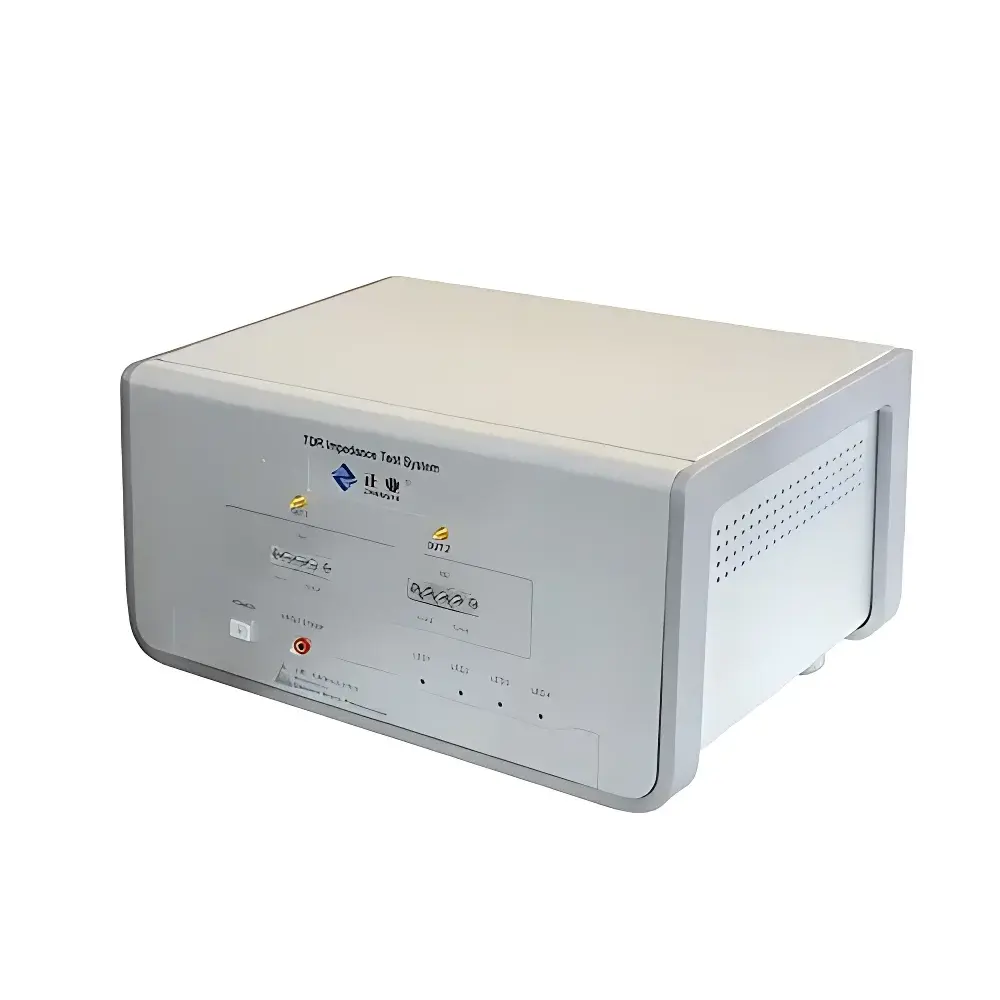
ZK3185 Differential High-Frequency PCB & Cable TDR Impedance Analyzer
| Brand | Zhengye |
|---|---|
| Origin | Guangdong, China |
| Manufacturer Type | OEM/ODM Producer |
| Country of Origin | China |
| Model | ZK3185 |
| Price | Upon Request |
| Impedance Measurement Range | 20–200 Ω |
| Measurement Length | 0.02–2 m |
| Bandwidth | 0.1–8.5 GHz |
| TDR Accuracy | ±1% @ 50 Ω |
| Measurement Speed | ≤1 s per point |
| S-Parameter Capability | Yes |
| Dynamic Range | >100 dB |
| Calibration | Full user-accessible multi-point calibration |
Overview
The ZK3185 Differential High-Frequency PCB & Cable TDR Impedance Analyzer is a time-domain reflectometry (TDR)-based instrument engineered for precision characterization of characteristic impedance in printed circuit boards (PCBs) and high-speed interconnects—including coaxial cables, twisted-pair wires, and flexible printed circuits. Operating across a bandwidth of 0.1–8.5 GHz, the analyzer leverages fast-rise-step TDR excitation with sub-nanosecond edge fidelity to resolve impedance discontinuities with spatial resolution down to ~1.8 cm (at 8.5 GHz). Its differential measurement architecture eliminates common-mode noise and enhances signal integrity during high-frequency trace analysis—critical for validating controlled-impedance routing in 5G RF modules, high-speed SerDes interfaces, and automotive ADAS harnesses. Designed for integration into QC labs and NPI validation workflows, the ZK3185 complies with industry-standard TDR methodology per IPC-TM-650 2.5.1 and supports traceability-aligned calibration protocols.
Key Features
- Differential TDR architecture with matched 50 Ω input/output ports for true balanced impedance profiling
- High-fidelity step generator with <100 ps rise time and low-jitter synchronization for repeatable waveform acquisition
- Multi-point user-accessible calibration suite—including open/short/load (OSL) and thru-reflect-line (TRL) options—enabling traceable impedance referencing per ISO/IEC 17025 requirements
- Integrated high-resolution sampling oscilloscope engine with 100 GS/s equivalent-time sampling rate
- Automated impedance profile extraction: calculates Z0, impedance deviation (ΔZ), and reflection coefficient (Γ) along the DUT length
- Onboard statistical engine supporting Cp/Cpk, min/max/mean/std dev, and histogram-based yield assessment per test point
- Export-ready data output in CSV, S1P/S2P touchstone formats, and PDF report templates compliant with internal QA documentation standards
Sample Compatibility & Compliance
The ZK3185 accommodates standard PCB coupons (IPC-2141A compliant), microstrip/stripline test structures, and wire/cable assemblies with SMA or 2.92 mm connectors. It supports both single-ended and differential pair configurations up to 2 m in length. The instrument meets electromagnetic compatibility (EMC) requirements per GB/T 18268.1–2010 (equivalent to IEC 61326-1) and operates within Class II safety limits. While not certified to UL or CE for standalone deployment in regulated production environments, its measurement methodology aligns with IPC-TR-579, JEDEC JESD62, and ASTM D257 Annex A5 for surface resistivity correlation. For GLP/GMP-regulated labs, audit trails and electronic signature support are available via optional firmware upgrade (v3.2+).
Software & Data Management
The embedded Windows-based control software provides real-time waveform visualization, impedance profile overlay, and comparative pass/fail threshold mapping against IPC-2141B nominal tolerances (±10% typical). All raw TDR waveforms, calibration coefficients, and metadata (operator ID, timestamp, environmental temp/humidity logs) are stored in an encrypted SQLite database with configurable retention policies. Export functions include batch generation of S-parameter files for EM simulation (e.g., HFSS, CST), CSV datasets for Minitab or JMP statistical analysis, and customizable PDF reports featuring company logo, test standard references, and operator sign-off fields. Audit trail functionality records all parameter changes, calibration events, and report generation actions—supporting FDA 21 CFR Part 11 readiness when deployed with network-authenticated user roles.
Applications
- Validation of impedance-controlled PCB stack-ups during fabrication release (e.g., 50 Ω single-ended, 100 Ω differential pairs)
- Root-cause analysis of impedance mismatches in high-speed digital interconnects (PCIe Gen5, USB4, DDR5)
- Quality assurance of automotive wiring harnesses per ISO 16750-2 mechanical stress + impedance stability testing
- R&D characterization of novel dielectric substrates (e.g., LCP, polyimide) under varying temperature/humidity conditions
- Supplier qualification audits requiring documented impedance repeatability (R&R) per AIAG MSA guidelines
- Failure analysis of solder joint voiding, trace width variation, or prepreg resin flow anomalies affecting Z0
FAQ
What standards does the ZK3185 comply with for PCB impedance verification?
It implements TDR methodology aligned with IPC-TM-650 2.5.1, IPC-2141B, and JEDEC JESD62; calibration traceability follows ISO/IEC 17025 principles.
Can the ZK3185 measure impedance of flex-rigid PCBs with dynamic bending?
Yes—provided mechanical fixtures maintain stable probe contact; recommended use with articulated micro-positioning stages for repeatable strain-state testing.
Is S-parameter data export compatible with commercial EM simulators?
Yes—S1P (single-ended) and S2P (differential) files are generated in Touchstone v1.0 format, directly importable into Ansys HFSS, Keysight ADS, and Cadence Sigrity.
Does the system support automated pass/fail decision logic based on user-defined tolerance bands?
Yes—threshold-based go/no-go evaluation is configurable per segment (e.g., “±7% over first 50 mm”, “±12% over remaining length”) and logged in audit trail.
What is the minimum measurable impedance discontinuity length at 8.5 GHz?
Spatial resolution is ~1.8 cm (full-width half-maximum), enabling detection of localized defects such as micro-vias, solder mask slivers, or etch undercut within defined test coupons.


