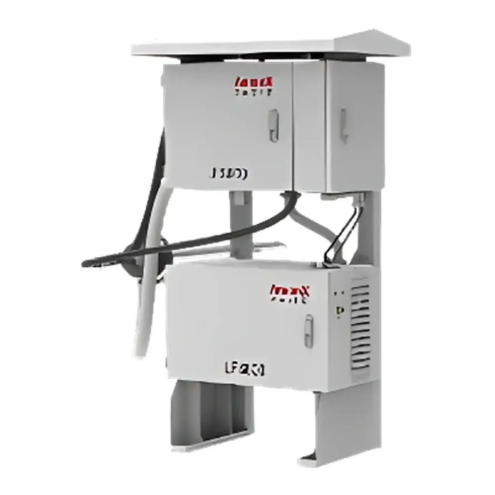
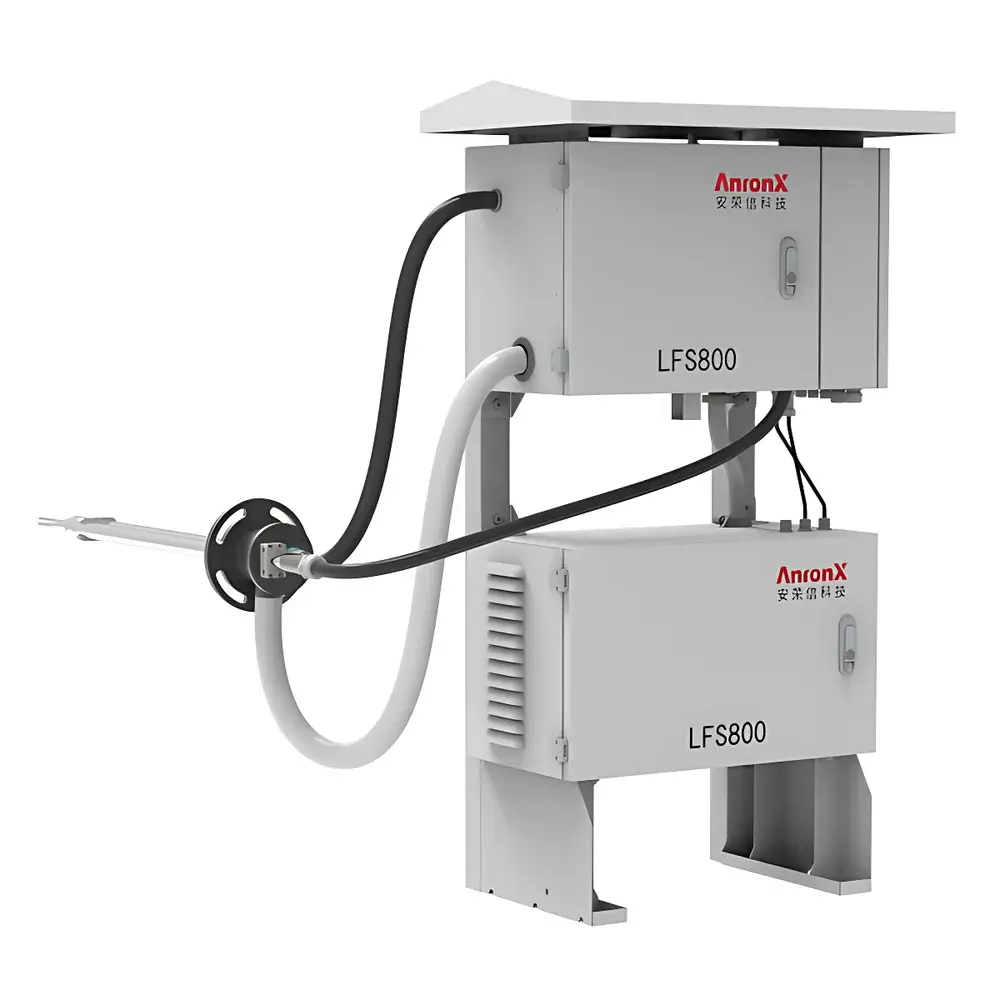
AnronX LFS800 Ultra-Low Particulate Matter Continuous Emission Monitoring System (CEMS)
| Brand | AnronX |
|---|---|
| Origin | Jiangsu, China |
| Model | LFS800 |
| Measurement Principle | Laser Forward Scattering |
| Sample Type | Wet Flue Gas |
| Measured Parameter | Particulate Matter (PM) |
| Range | 0–5 mg/m³ (Low Range), Dual-Range Auto-Switching |
| Detection Limit | 0.01 mg/m³ |
| Accuracy | ±10% (Gravimetric Reference Method) |
| Isokinetic Sampling Flow Rate | Up to 200 L/min |
| Heating | Full-Path Heated Sampling Line |
| Calibration | Automated Zero and Span Calibration |
| Display | Integrated LED Interface |
| Output | Analog 4–20 mA + Digital RS485/Modbus RTU |
| Compliance | Designed for China’s HJ 75–2017 & HJ 76–2017 CEMS Technical Specifications |
Overview
The AnronX LFS800 Ultra-Low Particulate Matter Continuous Emission Monitoring System (CEMS) is an extractive, in-situ compatible optical instrument engineered for real-time, high-stability measurement of suspended particulate matter (PM) concentrations in wet, low-emission flue gas streams. It operates on the principle of laser forward scattering photometry—where a collimated 650 nm semiconductor laser beam interacts with aerosol particles in the sampled gas stream, and the intensity of scattered light at a forward angle (typically 15°–30°) is quantitatively correlated to mass concentration via factory-established calibration curves traceable to gravimetric reference standards. Unlike opacity-based or beta attenuation methods, the LFS800 maintains linearity and sensitivity across ultra-low concentration ranges (0–5 mg/m³), making it suitable for post-SCR, post-FF, and wet FGD applications where regulatory limits fall below 5 mg/m³—consistent with China’s stringent “ultra-low emission” (ULE) policy framework under GB 13223–2011 and provincial implementation guidelines.
Key Features
- Extractive sampling architecture with full-path heated probe and transport line (maintained ≥120 °C), preventing condensation and wall deposition during transit of saturated flue gas;
- Isokinetic sampling control with integrated flow metering capability up to 200 L/min, optionally synchronized with external stack velocity signals for dynamic flow compensation;
- Dual-range auto-switching detection system: primary low-range mode (0–5 mg/m³) optimized for ULE compliance, with seamless transition to extended range (e.g., 0–50 mg/m³) when transient spikes occur;
- Optical detection module featuring temperature-stabilized laser diode, precision aperture alignment, and multi-point dark-current compensation to ensure long-term signal stability;
- Onboard automated calibration sequence: zero calibration using clean purge air (filtered to ISO Class 3), span calibration via certified PM reference aerosol generator (optional accessory); both executed without manual intervention;
- Embedded microcontroller with real-time LED interface displaying instantaneous PM concentration, sampling flow rate, heater status, optical path integrity, and fault diagnostics;
- Ruggedized industrial enclosure (IP65-rated) with modular internal layout—designed for minimal field maintenance intervals and tolerance to ambient temperatures from −20 °C to +50 °C.
Sample Compatibility & Compliance
The LFS800 is validated for continuous operation in flue gas environments containing moisture saturation, SO₂ (<1000 ppm), NOₓ (<500 ppm), and particulate loadings typical of coal-fired, biomass, and waste-to-energy combustion sources. Its heated sampling train enables reliable performance in dew-point conditions up to 60 °C. The system conforms to the functional and performance requirements outlined in HJ 75–2017 (Technical Specification for Continuous Emission Monitoring of Flue Gas) and HJ 76–2017 (Verification Procedures for CEMS), including 7-day drift ≤±2.5%, response time <120 s, and data capture rate ≥90%. While not certified to EN 15267 or US EPA PS-11, its gravimetric validation protocol aligns with ISO 12141:2021 (Stationary source emissions — Manual determination of mass concentration of particulate matter) as a reference method comparator.
Software & Data Management
The LFS800 outputs analog 4–20 mA signals (linear over full scale) and digital Modbus RTU via RS485 for integration into existing DCS or environmental data acquisition systems (e.g., SCADA, EMS). Local data logging (internal SD card, optional) retains 30 days of 1-minute averaged records with timestamps, operational status flags, and calibration event logs. All stored data include audit-trail metadata (user ID, action type, timestamp) to support basic GLP-aligned recordkeeping. Remote configuration and firmware updates are supported via secure serial interface; no cloud connectivity or proprietary software installation is required—ensuring compatibility with air-gapped industrial networks.
Applications
- Continuous monitoring of PM emissions from coal-fired power plants operating under ultra-low emission retrofit programs;
- Real-time compliance verification at cement kiln stacks equipped with fabric filters and wet electrostatic precipitators;
- Performance evaluation of particulate control devices (e.g., WESP efficiency testing under varying load conditions);
- Source testing support for environmental inspection agencies conducting periodic stack testing per HJ/T 397;
- Process optimization feedback loop in municipal solid waste incinerators where rapid PM transients correlate with combustion instability.
FAQ
Does the LFS800 require periodic optical cleaning or alignment?**
No—its forward-scatter optical path is sealed and purged with filtered air during operation; routine maintenance is limited to quarterly filter replacement and annual gravimetric verification.
Can the system measure PM₁₀ or PM₂.₅ speciation?**
No—the LFS800 reports total suspended particulate mass concentration (mg/m³) as a surrogate for regulatory PM reporting; it does not perform size-selective fractionation.
Is the instrument compatible with third-party data acquisition platforms?**
Yes—standard 4–20 mA analog output and Modbus RTU protocol enable interoperability with most industrial DAQ systems without custom drivers.
What is the recommended calibration frequency under HJ 76–2017?**
Zero and span calibration must be performed at least once every 7 days; automatic calibration cycles may be scheduled daily if configured with optional aerosol generator.
How is isokinetic sampling maintained when stack velocity varies?**
The system accepts external 4–20 mA velocity input (e.g., from a pitot tube or thermal anemometer) and dynamically adjusts sample pump speed to preserve constant Qs/Qt ratio per HJ/T 48–1999.