XRHGantry Industrial Micro-CT System by Visiconsult
| Brand | Visiconsult |
|---|---|
| Origin | Germany |
| Model | XRHGantry |
| Maximum Tube Voltage | 450 kV |
| Axes | 7 CNC-Programmable Motorized Axes |
| Detector Compatibility | Broad Spectrum (Flat-Panel, Line-Scan, High-Resolution Scintillator-Based) |
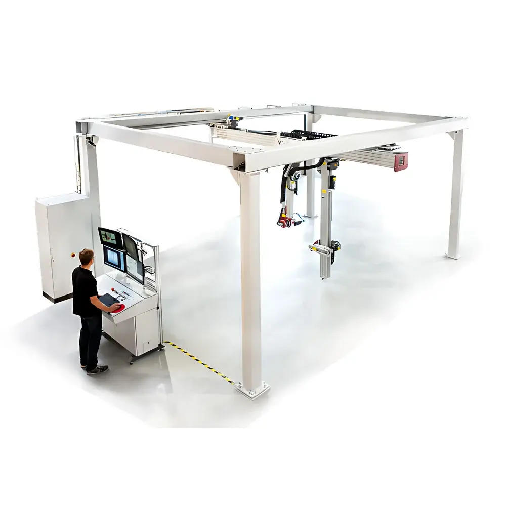
| Installation Type | Top-Mounted Gantry Configuration |
| Shielding Requirement | Lead-Lined Room or Dedicated Radiation-Shielded Enclosure |
| Custom Layout Support | Yes |
| Application Scope | Non-Destructive Inspection of Large & Complex Industrial Components |
Overview
The XRHGantry Industrial Micro-CT System, engineered by Visiconsult (Germany), is a top-mounted, fully integrated micro-computed tomography platform designed for high-fidelity non-destructive evaluation (NDE) of large-scale, geometrically complex, and high-density industrial components. Unlike conventional floor-mounted CT systems constrained by part weight, height, or rotational symmetry, the XRHGantry employs a vertically oriented gantry architecture with the X-ray source positioned above the inspection volume and the detector array below—enabling unobstructed access to oversized or irregularly shaped objects such as turbine blades, cast engine blocks, composite airframe sections, and welded pressure vessels. Its core measurement principle relies on cone-beam or fan-beam X-ray projection acquisition across multiple angular positions, followed by iterative reconstruction (e.g., FDK or SART algorithms) to generate isotropic 3D volumetric datasets with sub-millimeter spatial resolution. The system operates at up to 450 kV tube voltage, permitting penetration of dense metallic alloys (e.g., Inconel, Ti-6Al-4V, thick-walled steel) while maintaining sufficient photon flux for low-noise, high-contrast reconstruction.
Key Features
- Top-mounted gantry configuration with overhead X-ray source and under-table detector—optimized for vertical part loading and minimal floor space footprint.
- Seven independently controlled CNC-programmable axes: X/Y/Z linear translation, tilt (±15°), rotation (360° continuous), detector lateral shift, and source-to-detector distance adjustment—enabling precise trajectory planning for helical, circular, or customized scanning paths.
- Tilt axis functionality supports elliptical imaging geometry for double-wall weld inspection, eliminating superposition artifacts in pipe girth welds per ASTM E2737 and ISO 17636-2.
- Dynamically adjustable geometric magnification via motorized source–object–detector positioning, facilitating region-of-interest (ROI) zoom without hardware reconfiguration.
- Broad detector compatibility—including amorphous silicon flat-panel detectors (14-bit dynamic range), line-scan CCD/CMOS arrays, and high-light-yield scintillator modules—ensuring adaptability to throughput, resolution, and dose-efficiency requirements.
- Modular shielding integration: Designed for seamless installation within certified lead-lined rooms or custom-built concrete/steel radiation enclosures compliant with IEC 61331-1 and local regulatory limits (e.g., <1 µSv/h outside barrier).
Sample Compatibility & Compliance
The XRHGantry accommodates parts up to 1,200 mm in diameter and 2,000 mm in height (customizable), with maximum mass support exceeding 500 kg. It is routinely deployed for aerospace castings, automotive powertrain assemblies, additive-manufactured metal components, and nuclear fuel cladding samples. All operational parameters—including exposure time, tube current, filtration, and reconstruction kernel selection—are logged with timestamped metadata to satisfy GLP/GMP documentation requirements. System software supports audit trail generation and user access control aligned with FDA 21 CFR Part 11 for regulated quality assurance environments. Compliant with ISO 15708-1 (quantitative CT), EN 16018 (industrial CT terminology), and ASTM E1441 (computed tomography standard guide).
Software & Data Management
Control and reconstruction are executed via Visiconsult’s proprietary X-Ray Control Suite (XRCS), a Windows-based application supporting real-time projection monitoring, automated beam hardening correction, ring artifact suppression, and GPU-accelerated FDK reconstruction. Reconstructed volumes (DICOM-CT or raw HDF5 format) integrate natively with third-party analysis platforms including Volume Graphics VGStudio MAX, Thermo Scientific Avizo, and open-source tools like Dragonfly or ImageJ/Fiji. Project data—including scan protocols, calibration logs, and QA reports—is stored in a relational database with role-based permissions, version control, and export options compliant with ASME BPVC Section V, Article 24 traceability mandates.
Applications
- Dimensional metrology of internal geometries (e.g., wall thickness mapping, porosity quantification per ASTM E1559)
- Weld integrity assessment—including lack-of-fusion, slag inclusion, and crack morphology in multi-pass circumferential joints
- Pore network analysis in additively manufactured AlSi10Mg or 316L stainless steel parts
- Composite delamination and fiber orientation validation in carbon-fiber-reinforced polymer (CFRP) laminates
- Failure analysis of thermally cycled turbine vanes using longitudinal 4D-CT (time-resolved structural evolution)
- Reverse engineering of legacy components lacking CAD models
FAQ
What safety certifications does the XRHGantry require for facility installation?
Radiation shielding design must comply with national regulations (e.g., NRC 10 CFR 20 in the US, StrlSchV in Germany) and undergo third-party survey verification prior to commissioning.
Can the system perform in-situ thermal or mechanical loading during scanning?
Yes—optional integration with environmental chambers (−40°C to 300°C) and tensile/compression stages enables operando CT experiments under controlled stress or temperature conditions.
Is remote operation supported for distributed QA teams?
Full remote desktop control, secure DICOM data streaming, and web-based report dashboards are available via optional XRCS Enterprise License.
How is geometric calibration maintained across long-term deployments?
System includes automated daily phantom-based calibration routines using NIST-traceable step wedges and sphere phantoms; results are archived and trended for preventive maintenance alerts.
Does Visiconsult provide application-specific protocol development?
Yes—application engineers collaborate on method development, including scan parameter optimization, reconstruction pipeline tuning, and acceptance testing per customer-defined CTQs (Critical-to-Quality characteristics).


