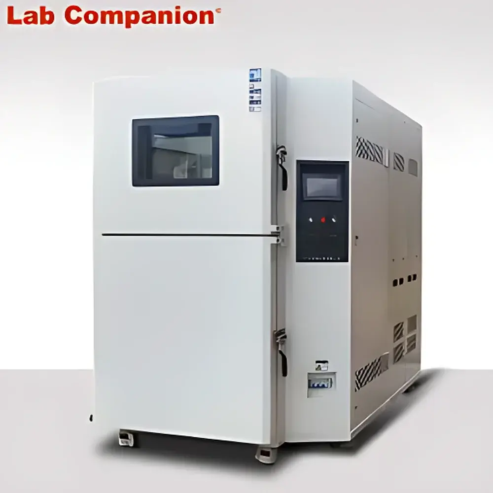
LabCompanion TS Two-Zone Thermal Shock Test Chamber
| Brand | LabCompanion |
|---|---|
| Origin | Guangdong, China |
| Manufacturer Type | Direct Manufacturer |
| Model | TS |
| High-Temperature Range | +150 °C |
| Low-Temperature Range | −65 °C |
| Thermal Shock Range | −65 °C to +150 °C |
| Heating Rate | ≤ 60 min (RT to +220 °C in hot zone, ambient 10–30 °C) |
| Cooling Rate | ≤ 90 min (RT to −80 °C in cold zone, ambient 10–30 °C) |
| Standard Internal Volumes | 36 L, 80 L, 150 L, 225 L |
| Custom Volume Range | 36 L to 8000 L |
| Temperature Exposure Range Options | −40 °C to +150 °C (CT model) |
Overview
The LabCompanion TS Two-Zone Thermal Shock Test Chamber is an engineered environmental stress screening system designed for rapid, repeatable thermal cycling between extreme high- and low-temperature environments. It operates on the two-basket (elevator-type) thermal shock principle: test specimens are mechanically transferred between thermally isolated hot and cold chambers via a precision-guided lift mechanism, enabling abrupt temperature transitions without intermediate air mixing. This architecture eliminates thermal inertia associated with single-chamber forced-air systems and ensures true step-change exposure—critical for evaluating solder joint integrity, polymer embrittlement, coating adhesion loss, and interfacial delamination in electronic assemblies, aerospace composites, and automotive power modules. The chamber complies with core test standards including MIL-STD-810H Method 503.7, JEDEC JESD22-A104F, IEC 60068-2-14, and ASTM D6277, supporting qualification-level reliability testing under controlled, auditable conditions.
Key Features
- Two-zone independent thermal control: Separate hot and cold chambers maintain stable setpoints (±0.5 °C uniformity) while minimizing cross-contamination via sealed transfer path and purge-assisted basket transition.
- High-speed thermal transition: Achieves ≤ 15-second specimen transfer time between zones; typical temperature overshoot < ±3 °C during dwell stabilization per IEC 60068-2-14 requirements.
- Robust mechanical architecture: Stainless-steel lift mechanism with servo-driven positioning, rated for >500,000 cycles; reinforced insulation (150 mm polyurethane foam, 0.2 W/m·K thermal conductivity) minimizes energy drift during long-duration shock profiles.
- Programmable shock profiles: Supports up to 999 cycles with user-defined dwell times (1 min–999 h), transition intervals, and sequence logic (e.g., “hot → cold → hot” or alternating ramp-dwell patterns).
- Integrated safety systems: Dual redundant over-temperature/over-pressure cutouts, liquid nitrogen interlock (optional), door-open inhibition, and real-time chamber pressure monitoring to prevent condensation-induced thermal shock anomalies.
Sample Compatibility & Compliance
The TS series accommodates samples up to 450 mm × 450 mm × 450 mm (W×D×H) in standard configurations, with custom internal dimensions scalable to 2000 mm × 2000 mm × 2000 mm (8000 L volume). Compatible with PCBs, wafer-level packages, battery modules, optical sensors, and molded plastic housings. All models meet CE marking requirements per 2014/30/EU (EMC) and 2014/35/EU (LVD), and support GLP/GMP-compliant validation protocols—including IQ/OQ/PQ documentation templates, sensor calibration traceability to NIST standards, and audit-ready event logging. Optional upgrades include ISO 17025-accredited calibration certificates and FDA 21 CFR Part 11-compliant electronic signature modules for regulated pharmaceutical and medical device applications.
Software & Data Management
Controlled via LabCompanion’s TC-Link™ Windows-based software, the TS chamber provides synchronized multi-channel data acquisition (up to 16 external thermocouple inputs), real-time graphical profiling, and automated report generation in PDF/CSV formats. Software features include deviation alarm thresholds, trend analysis with statistical process control (SPC) charts (X̄-R, Cpk), and secure role-based access (admin/operator/viewer). All operational events—including door openings, temperature deviations >±2 °C, and emergency stops—are timestamped and stored with SHA-256 hash integrity verification. Data export supports ASTM E2918-compliant metadata tagging for laboratory information management system (LIMS) integration.
Applications
- Accelerated life testing of lead-free solder joints under JEDEC JESD22-A104F thermal cycling stress.
- Qualification of EV battery enclosures per UN ECE R100 and ISO 16750-4 thermal shock durability requirements.
- Evaluation of optical adhesive bond strength in lidar modules exposed to −65 °C/+150 °C cycling.
- Material screening for space-grade polymers under MIL-STD-202G Method 107 (thermal shock).
- Failure mode analysis of MEMS packaging using accelerated thermal gradient-induced stress mapping.
FAQ
What is the difference between two-zone and three-zone thermal shock configurations?
The two-zone (TS) system uses physical specimen transfer between hot and cold chambers; the three-zone (TTS) variant adds a dedicated ambient soak zone for pre-conditioning—reducing thermal lag and improving repeatability for ultra-sensitive optoelectronic devices.
Can the chamber be validated for GMP environments?
Yes—optional 21 CFR Part 11 compliance package includes electronic audit trails, biometric login, and calibrated Class A PT100 sensors with annual recalibration certification.
Is nitrogen purging supported for moisture-sensitive tests?
Standard configuration includes dry-air purge; optional LN₂ or compressed N₂ inert gas manifold enables dew point control down to −70 °C for semiconductor wafer-level testing.
What maintenance intervals are recommended?
Compressor oil and refrigerant filter replacement every 24 months; chamber seal inspection and thermocouple calibration annually; full system performance verification per ISO/IEC 17025 every 12 months.
How is temperature uniformity verified across large custom chambers?
Validation performed using 9-point sensor mapping per IEC 60068-3-5, with spatial deviation reported as maximum deviation from setpoint at all locations during steady-state dwell periods.


