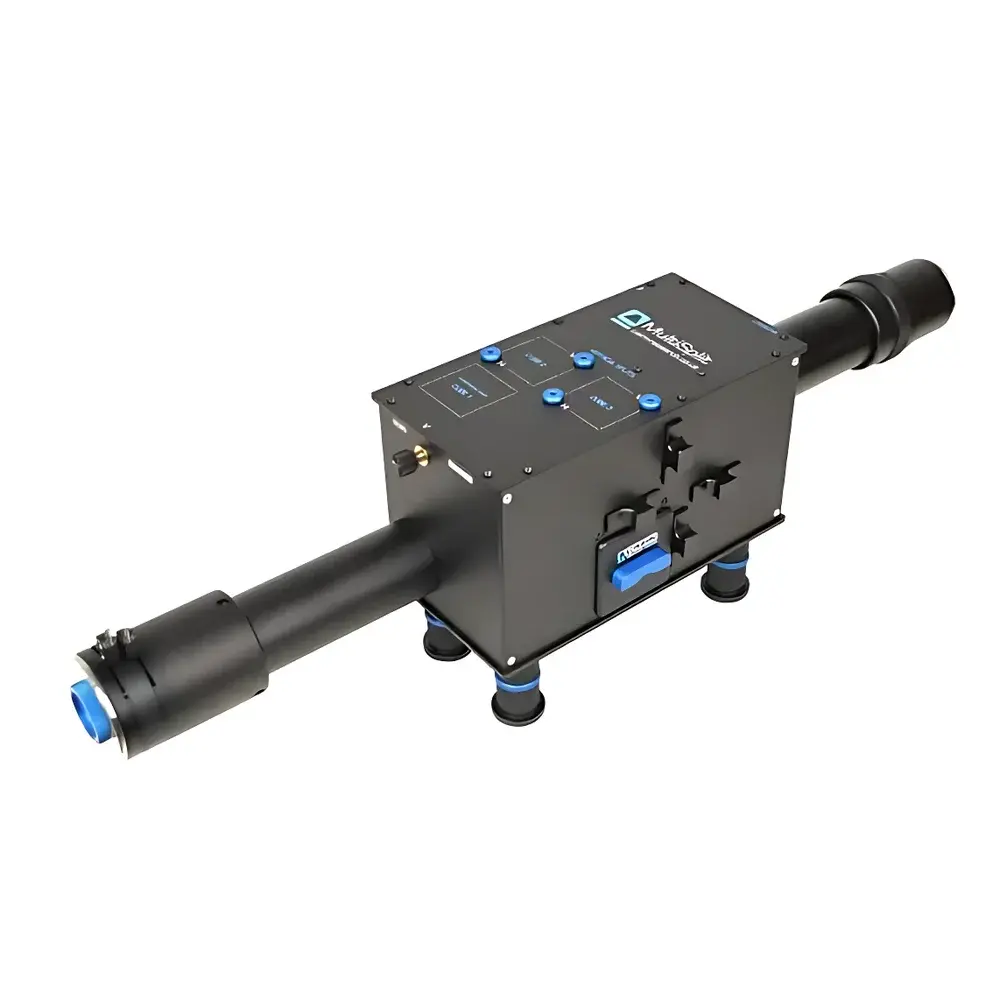
Cairn Multisplit V2 Four-Channel Image Splitter
| Brand | Cairn |
|---|---|
| Origin | United Kingdom |
| Manufacturer Type | Authorized Distributor |
| Import Status | Imported |
| Model | Multisplit V2 |
| Pricing | Available Upon Request |
Overview
The Cairn Multisplit V2 is a precision-engineered four-channel image splitter designed for advanced multimodal fluorescence microscopy and quantitative optical imaging. It operates on the principle of spatial beam division using dichroic mirrors and emission filters, enabling simultaneous acquisition of up to four spectrally or polarization-resolved image channels from a single objective port. Unlike sequential filter wheel-based approaches—which introduce temporal latency, motion artifacts, and synchronization overhead—the Multisplit V2 delivers true temporal co-registration across all output paths. This capability is essential for dynamic intracellular assays such as Förster Resonance Energy Transfer (FRET), ratiometric ion imaging (Ca²⁺, H⁺, membrane voltage), and polarization anisotropy measurements where sub-millisecond inter-channel timing fidelity directly impacts quantitative accuracy. The device integrates seamlessly into inverted and upright microscope configurations and supports high-speed sCMOS and EMCCD cameras without requiring frame buffering or complex software triggering.
Key Features
- Four-channel parallel image splitting with configurable spectral or polarization routing
- Standard C-mount input and output interfaces; optional F-mount and T-mount adapters available upon request
- Optimized for sensor diagonals up to 29.4 mm—compatible with full-frame and large-format scientific cameras
- All optical surfaces feature broadband anti-reflection (AR) coating spanning 425–875 nm, minimizing ghosting and maximizing throughput across visible and near-infrared bands
- Proprietary 40 mm diameter optics ensure uniform wavefront transmission and minimal distortion across all split channels
- Emission filter slots accept standard 25 mm diameter round filters; dichroic mirror mounts accommodate 26 × 38 × 2 mm optics with λ/2 surface flatness specification
- Magnetic cube housing enables rapid, repeatable alignment and mechanical stability under vibration-prone conditions
- Interchangeable filter/dichroic carrier system allows in-lab reconfiguration for new experimental modalities without recalibration
- Optional polarization-splitting kit includes Glan-Taylor polarizing beam splitter cubes and motorized or manual rotation stages for precise azimuthal control
Sample Compatibility & Compliance
The Multisplit V2 is compatible with live-cell preparations, fixed tissue sections, microfluidic devices, and optically cleared specimens. Its passive optical architecture introduces no electronic noise, thermal drift, or timing jitter—ensuring compliance with GLP/GMP-aligned imaging workflows where traceability and reproducibility are critical. While the device itself carries no active regulatory certification, its optical design adheres to ISO 10110-7 standards for coated optical components and meets mechanical tolerance specifications outlined in ISO 9001-compliant manufacturing protocols. When integrated into FDA-regulated systems (e.g., clinical research microscopes), the splitter contributes to audit-ready documentation by eliminating software-dependent synchronization layers that complicate 21 CFR Part 11 validation.
Software & Data Management
The Multisplit V2 requires no proprietary drivers or firmware. It functions transparently with all major acquisition platforms—including Micro-Manager, MetaMorph, NIS-Elements, and ZEN—via standard camera SDKs. Spatial registration between split channels is maintained through mechanical alignment rather than software correction, reducing post-processing computational load and preserving native pixel resolution. Users may employ open-source tools (e.g., Python-based nd2reader, tifffile) to extract and align channel-specific TIFF stacks. For quantitative applications such as FRET efficiency calculation or polarization ratio mapping, the device’s intrinsic pixel-to-pixel correspondence eliminates the need for affine transformation matrices, thereby improving measurement repeatability across instrument platforms and laboratories.
Applications
- Förster Resonance Energy Transfer (FRET) quantification with donor–acceptor pair separation in real time
- Ratiometric calcium, pH, and voltage imaging using dual-emission probes (e.g., Indo-1, Fura-2, ArcLight)
- Simultaneous multi-fluorophore tracking in super-resolution modalities including PALM and STORM
- TIRF and spinning-disk confocal microscopy with orthogonal channel monitoring (e.g., structural marker + functional reporter)
- Polarization-resolved imaging for molecular orientation analysis and fluorescence anisotropy decay studies
- Combined phase contrast/DIC and fluorescence acquisition for correlative morphology–function assessment
- Synchronized dual-Z-depth imaging for rapid axial sectioning without piezo stage movement
- Single-plane illumination microscopy (SPIM) and light-sheet setups requiring multi-angle detection paths
FAQ
Does the Multisplit V2 require external power or control electronics?
No—it is a fully passive optical device with no electrical components, eliminating EMI concerns and simplifying integration into shielded or low-noise environments.
Can I use custom dichroics or filters not supplied by Cairn?
Yes—filter holders accept industry-standard dimensions; users may install third-party optics provided they meet specified thickness, flatness, and clear aperture requirements.
How is spatial alignment between channels verified and maintained?
Alignment is factory-set using interferometric verification and secured via magnetic retention; periodic checks can be performed using a 1951 USAF resolution target imaged through all ports simultaneously.
Is the Multisplit V2 compatible with resonant scanning or line-scanning confocals?
Yes—its static optical path introduces no latency or dispersion, making it suitable for high-duty-cycle scanning systems where timing-critical synchronization is required.
What is the maximum working distance between the splitter and camera sensor?
When used with standard C-mount extensions, the optical path length remains within telecentric constraints for sensors up to 29.4 mm diagonal; longer paths may require relay lens correction to maintain field flatness.