EKSMA Nd:YAG Laser Beamsplitters
| Brand | EKSMA |
|---|---|
| Substrate Material | BK7 or UV Fused Silica (UVFS) |
| Design Wavelengths | 266 nm, 355 nm, 532 nm, 1064 nm |
| Beam Splitting Ratio | 50:50 (R/T ≈ 50% ± 3% averaged over s- and p-polarizations) |
| Dimensions | Ø12.7 mm × 3 mm or Ø25.4 mm × 6 mm |
| Surface Quality | λ/10 @ 633 nm |
| Flatness | λ/20 @ 633 nm |
| Coating Type | Dielectric, Broadband or Wavelength-Specific AR/HR on Back Surface |
| Damage Threshold | >500 MW/cm² (10 ns, 10 Hz, 1064 nm) |
Overview
EKSMA Nd:YAG Laser Beamsplitters are precision dielectric thin-film optical components engineered for high-stability beam division in pulsed and CW Nd:YAG laser systems. Designed around the fundamental principles of interference-based amplitude splitting, these beamsplitters operate via a multilayer dielectric coating deposited on optically polished substrates—ensuring minimal wavefront distortion and polarization-dependent loss. Unlike metallic coatings, the dielectric architecture delivers superior transmission and reflection uniformity across s- and p-polarization states, enabling consistent 50:50 splitting (R ≈ T ≈ 50%, where R = (Rs + Rp)/2 and T = (Ts + Tp)/2) at designated harmonic wavelengths (266 nm, 355 nm, 532 nm, and 1064 nm). The components are optimized for use in interferometric setups, cavity dumping configurations, pump-probe experiments, and dual-path alignment systems where precise spatial separation and phase coherence preservation are critical.
Key Features
- High-precision dielectric coatings with ±3% uniformity in R/T ratio across both s- and p-polarizations at design wavelengths
- Choice of optical substrates: BK7 glass for 532 nm and 1064 nm applications; UV-grade fused silica (UVFS) for deep-UV operation (266 nm, 355 nm) and enhanced laser-induced damage resistance
- Surface flatness ≤ λ/20 @ 633 nm and surface quality ≤ λ/10 @ 633 nm — compliant with ISO 10110-7 standards for precision optics
- High laser damage threshold: >500 MW/cm² (10 ns pulse width, 10 Hz repetition rate, 1064 nm), validated per ISO 21254-1
- Standard geometries: Ø12.7 mm × 3 mm and Ø25.4 mm × 6 mm—compatible with industry-standard kinematic mounts and lens tubes (e.g., Thorlabs SM1/SM2 series)
- Back-surface anti-reflection (AR) or high-reflection (HR) coatings available to suppress ghost reflections and improve system contrast
Sample Compatibility & Compliance
These beamsplitters are compatible with standard Nd:YAG laser platforms operating in fundamental (1064 nm) and harmonic (532 nm, 355 nm, 266 nm) regimes—including Q-switched nanosecond systems (e.g., Continuum Surelite, Quantel Brilliant), diode-pumped solid-state lasers (e.g., Spectra-Physics Quanta-Ray), and ultrafast amplifier front-ends requiring stable seed beam routing. All units conform to RoHS Directive 2011/65/EU and are manufactured under ISO 9001-certified processes. Substrate material selection and coating specifications align with ASTM F1281 (optical component cleanliness) and MIL-PRF-13830B scratch-dig requirements. Documentation includes individual test reports for surface flatness, spectral performance, and LIDT verification—supporting GLP-compliant optical system validation.
Software & Data Management
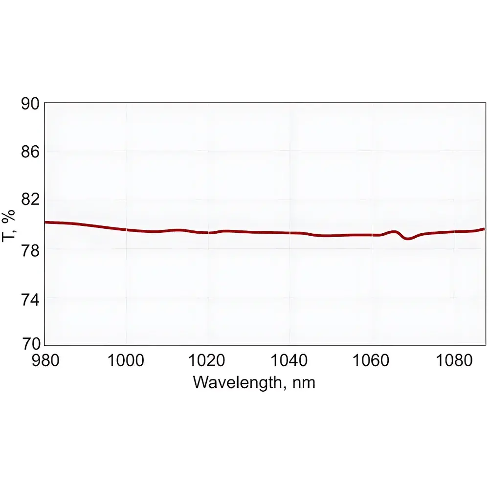
While EKSMA Nd:YAG Laser Beamsplitters are passive optical elements and require no embedded firmware or driver software, comprehensive technical documentation is provided in digital format (PDF) including spectral reflectance/transmittance curves (250–1100 nm), angular acceptance data (±2° tolerance), and environmental stability metrics (thermal coefficient of expansion matched to substrate). For integration into automated optical benches, dimensional and mounting data are supplied in STEP and IGES formats. Traceable calibration certificates—referencing NIST-traceable interferometric metrology—are available upon request to support FDA 21 CFR Part 11–aligned instrument qualification protocols in regulated R&D environments.
Applications
- Beam sampling and power monitoring in high-energy Nd:YAG laser cavities
- Interferometric diagnostics (e.g., Mach–Zehnder, Michelson) requiring polarization-insensitive splitting
- Pump–probe spectroscopy setups utilizing time-delayed 1064 nm/532 nm beam pairs
- Harmonic generation alignment stations (e.g., SHG, THG, FHG) where spatial overlap and intensity balance are critical
- Laser safety interlock paths and redundant beam detection circuits
- Optical parametric oscillator (OPO) seeding and signal/idler path separation
FAQ
Are these beamsplitters polarization-sensitive?
No—they are engineered for polarization-averaged 50:50 splitting (R = (Rs + Rp)/2, T = (Ts + Tp)/2), minimizing dependence on incident polarization state within ±2° angular tolerance.
Can I use the same beamsplitter for both 1064 nm and 532 nm simultaneously?
Not recommended. Each variant is optimized for a specific wavelength band. Using a 1064 nm–designed beamsplitter at 532 nm results in significant deviation from nominal R/T and increased absorption-induced thermal lensing.
What is the maximum incident angle for optimal performance?
The specified R/T ratio and phase relationship hold within ±2° of normal incidence. Beyond this range, polarization splitting asymmetry increases, and coating performance degrades per Fresnel equations.
Do you provide custom coating specifications or non-standard dimensions?
Yes—EKSMA offers OEM services including custom AR/HR back-surface treatments, wedge-free variants, and substrate thickness adjustments. Lead time and MOQ apply; contact technical sales for feasibility assessment.
Is LIDT testing performed per ISO 21254?
Yes—each production lot undergoes representative LIDT screening using calibrated 1064 nm nanosecond pulses per ISO 21254-1, with full test reports available upon request.