Few-Mode Erbium-Doped Fiber Amplifier (EDFA) – MODE-GAP Series, C-Band (1535–1560 nm)
| Origin | UK |
|---|---|
| Manufacturer Type | Authorized Distributor |
| Origin Category | Imported |
| Operating Band | C-band (1535–1560 nm) |
| Mode Configurations | 3-mode (LP₀₁, LP₁₁ₐ, LP₁₁_b) or 6-mode (LP₀₁, LP₁₁ₐ, LP₁₁_b, LP₂₁ₐ, LP₂₁_b, LP₀₂) |
| Pump Port Flexibility | User-Configurable for Mode-Group–Selective Pumping |
| Noise Figure | <5.0 dB (typ., per mode) |
| Small-Signal Gain | >25 dB (typ., full band, all modes) |
| Differential Modal Gain (DMG) | <1.5 dB across C-band |
| Polarization-Dependent Gain | <0.3 dB |
Overview
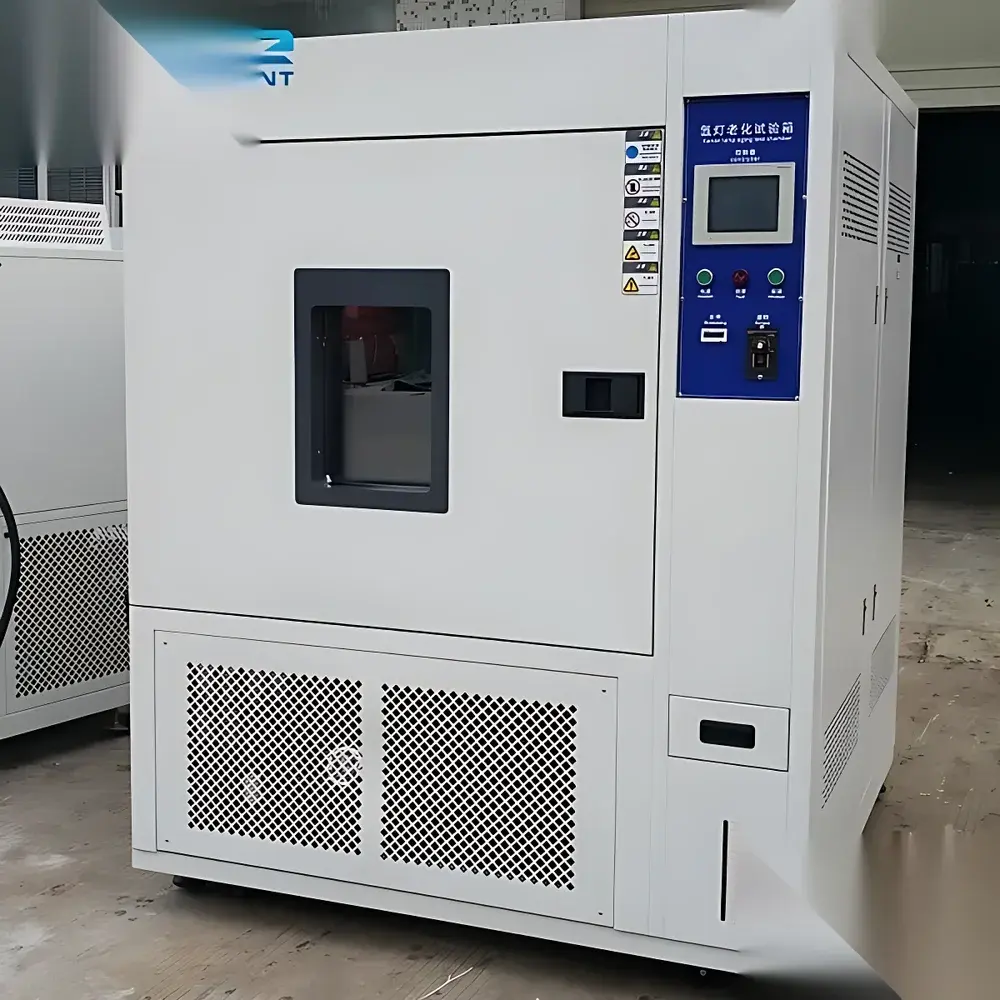
The Few-Mode Erbium-Doped Fiber Amplifier (EDFA) – MODE-GAP Series is a research-grade optical amplifier engineered for spatial division multiplexing (SDM) systems and mode-division multiplexed (MDM) transmission experiments. Developed under the European Union–funded MODE-GAP project, this amplifier operates in the conventional C-band (1535–1560 nm) and supports discrete guided modes in few-mode fiber (FMF) infrastructure. Unlike standard single-mode EDFAs, it preserves modal orthogonality while delivering uniform gain across multiple linearly polarized (LP) mode groups—enabling precise characterization of mode-dependent loss, modal crosstalk, and amplification dynamics in next-generation multimode optical networks.
Key Features
- Mode-selective amplification architecture supporting either 3-mode (LP01, LP11a, LP11b) or 6-mode (LP01, LP11a, LP11b, LP21a, LP21b, LP02) configurations
- Low differential modal gain (DMG) of <1.5 dB across the entire C-band, ensuring balanced power evolution among co-propagating modes
- Integrated pump port customization: users define the number and spatial arrangement of 980 nm or 1480 nm pump inputs to enable mode-group–resolved gain control
- High small-signal gain (>25 dB) with noise figure <5.0 dB (typical, per supported mode), validated via calibrated optical spectrum analyzer (OSA) and mode-resolved photodetection setups
- Thermally stabilized erbium-doped few-mode fiber coil with optimized length and doping profile to minimize mode coupling and nonlinear penalties
- Front-panel and remote (RS232/USB/Ethernet) interface for real-time monitoring of pump current, output power per mode group (via integrated tap couplers), and internal temperature
Sample Compatibility & Compliance
This amplifier is designed for integration into laboratory-scale SDM testbeds using standard step-index or graded-index few-mode fibers with core diameters of 15–25 µm and NA ≈ 0.12–0.16. It accepts polarization-maintaining (PM) and non-PM FMF pigtails with FC/APC or SC/APC connectors. All optical components comply with IEC 61300-2-4 (fiber optic connector durability) and IEC 60825-1 (laser safety Class 1M). The unit meets CE marking requirements for electromagnetic compatibility (EN 55032, EN 55035) and low-voltage directive (2014/35/EU). Firmware supports audit-ready logging for GLP-compliant optical characterization workflows.
Software & Data Management
The amplifier includes embedded firmware with dual operating modes: manual gain setpoint control and automatic mode-balanced gain lock. A Windows/Linux-compatible GUI application provides real-time visualization of gain spectra per mode group, pump efficiency maps, and DMG drift over time (±0.05 dB resolution). Export formats include CSV, HDF5, and MATLAB .mat—facilitating post-processing with mode decomposition algorithms (e.g., principal mode analysis, MIMO channel estimation). Data logs include timestamps, environmental sensor readings (T, RH), and user-defined metadata tags, satisfying traceability requirements under ISO/IEC 17025 and FDA 21 CFR Part 11 for regulated R&D environments.
Applications
- Experimental validation of mode-division multiplexed transceivers in datacenter interconnects
- Characterization of mode-dependent gain saturation and cross-gain modulation in FMF-based amplifiers
- Calibration source for mode-selective photonic lanterns and multi-plane light conversion (MPLC) devices
- Test platform for evaluating mode-coupling mitigation strategies in bent or spliced FMF segments
- Supporting research in orbital angular momentum (OAM) mode amplification when combined with OAM mode sorters
- Enabling closed-loop adaptive gain equalization in reconfigurable SDM network nodes
FAQ
What mode groups are supported, and how are they excited?
The amplifier supports either 3-mode (LP01, LP11a, LP11b) or 6-mode (LP01, LP11a, LP11b, LP21a, LP21b, LP02) operation. Input excitation must be provided externally via mode-selective launch optics (e.g., photonic lanterns, spatial light modulators, or phase plates); the amplifier itself does not generate or convert modes.
Can the pump configuration be modified after purchase?
Yes—pump port layout (number and angular orientation) is defined at order entry. Hardware-level reconfiguration requires factory service; however, firmware allows dynamic allocation of pump power among available ports during operation.
Is the amplifier compatible with ITU-T G.650.2 mode field diameter specifications?
It is optimized for FMFs meeting ITU-T G.650.2 Annex D (few-mode fiber definitions), particularly those with effective mode field diameters of 10.5 ± 0.8 µm for LP01 and 16.2 ± 1.0 µm for LP21 at 1550 nm.
Does the unit support automatic gain control (AGC) per mode group?
AGC is implemented at the aggregate output level. Mode-group–resolved AGC requires external feedback from mode-demultiplexed receivers and is supported via analog voltage input (0–5 V) on the rear panel.
What documentation is provided for metrological traceability?
Each unit ships with a factory calibration report referencing NPL-traceable power meters and wavelength standards, including measured gain flatness, noise figure vs. wavelength, and DMG sweep data across the C-band.