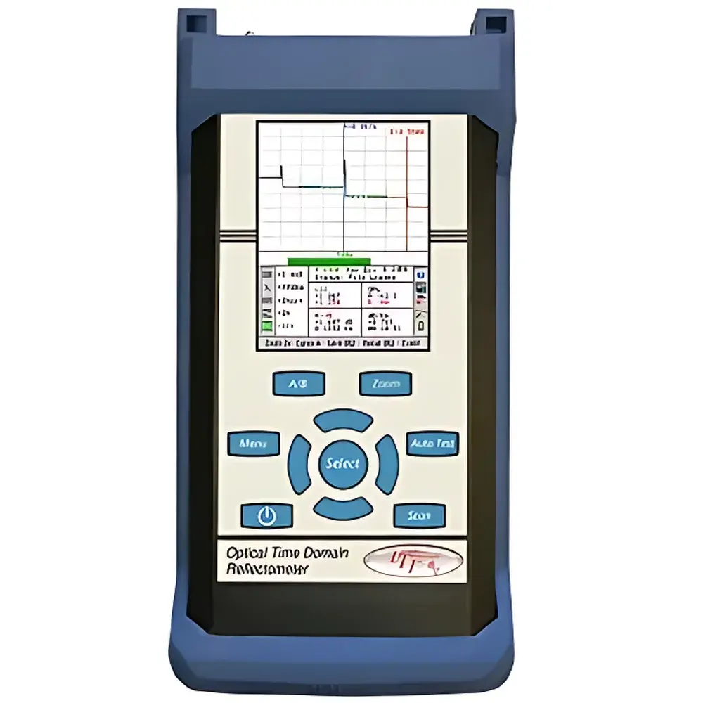
TTI FTE-7000 Optical Time-Domain Reflectometer
| Brand | TTI |
|---|---|
| Origin | USA |
| Model | FTE-7000 |
| Wavelengths | 850, 1300, 1310, 1550 nm ±20 nm |
| Dynamic Range | 27/26 dB (MM), 32/30 dB (SM) |
| Event Dead Zone | 2 m |
| Attenuation Dead Zone | 5 m |
| Distance Range | 1–64 km (MM), 1–240 km (SM) |
| Pulse Width | 20–10,000 ns |
| Resolution | 0.25–64 m |
| Distance Uncertainty | ±(0.75 m + 0.005% × distance + sampling resolution) |
| Sampling Rate | 4 Hz typical real-time refresh |
| Refractive Index Range | 1.024–2.048 |
| Linearity | ±0.05 dB/dB |
| Onboard Storage | 1,000 traces |
| Battery Life | 4 hours |
| Operating Temperature | −10 to 50 °C |
| Storage Temperature | −20 to 60 °C |
| Dimensions (L×W×H) | 194 × 99 × 40 mm |
| Weight | 0.73 kg |
| Interface | USB |
| Connector Types | Interchangeable FC/ST/SC |
| Included Software | Windows-based Telcordia SR-4731 compliant OTDR analysis suite |
Overview
The TTI FTE-7000 Optical Time-Domain Reflectometer (OTDR) is a field-deployable, high-performance fiber optic characterization instrument engineered for precision fault location, loss measurement, and end-to-end link validation in single-mode (SM) and multimode (MM) optical networks. Based on the principle of time-resolved backscattered light detection—specifically Rayleigh scattering and Fresnel reflections—the FTE-7000 injects calibrated laser pulses into the fiber under test and analyzes the amplitude and temporal delay of returned signals to generate distance-resolved attenuation profiles. Its architecture supports standardized wavelength operation at 850 nm, 1300 nm, 1310 nm, and 1550 nm (±20 nm), enabling compliance with ITU-T G.652, G.655, and IEC 61280-4-1 test methodologies. Designed for telecom infrastructure build-out, FTTx rollout, and enterprise LAN maintenance, the FTE-7000 delivers deterministic spatial resolution down to 0.25 m and maintains trace fidelity across dynamic ranges up to 32 dB in SM fiber—sufficient to characterize links exceeding 240 km without repeater assistance.
Key Features
- Short event dead zone of 2 meters—enabling reliable detection of closely spaced connectors, splices, and patch panel faults
- Integrated Light Source (LTS) functionality for bidirectional insertion loss verification per IEC 61280-4-2
- Embedded Visual Fault Locator (VFL) at 650 nm for rapid macrobend and break identification
- One-touch automated measurement with real-time trace averaging at up to 4 Hz refresh rate
- Pass/fail event reporting aligned with Telcordia GR-196-CORE and SR-4731 criteria
- Overlaid trace comparison mode for pre- and post-installation change detection
- Ruggedized magnesium alloy chassis with IP54-rated rubber overmold for field durability
- Interchangeable FC, ST, and SC adapter sleeves—no tooling required
- Onboard storage for 1,000 full-resolution OTDR traces with timestamped metadata
- USB 2.0 interface supporting direct export to Windows-based analysis platforms
Sample Compatibility & Compliance
The FTE-7000 is validated for use with standard ITU-T G.652.D, G.655, and OM1–OM5 multimode fibers. It supports both ribbon and loose-tube cable configurations and accommodates launch and receive cables via universal adapter sleeves. All firmware and measurement algorithms conform to industry-standard calibration traceability requirements defined in ISO/IEC 17025-accredited laboratories. The device meets electromagnetic compatibility (EMC) per FCC Part 15 Class B and CE Directive 2014/30/EU. Software-generated reports include audit-ready fields for operator ID, fiber ID, date/time stamp, refractive index setting, and pulse width—supporting GLP-compliant documentation workflows. While not certified for FDA 21 CFR Part 11, its trace export architecture enables integration into validated LIMS environments where electronic signature and audit trail functions are externally managed.
Software & Data Management
Supplied with Windows-compatible Telcordia SR-4731-compliant analysis software, the FTE-7000 enables comprehensive trace interpretation, splice/connector loss calculation, reflectance quantification, and event table generation. The software supports batch processing of multiple traces, automatic event classification (e.g., “good splice”, “high-loss connector”, “fiber end”), and customizable pass/fail thresholds per link segment. Export formats include .csv (for spreadsheet analysis), .pdf (for customer-facing reports), and .sor (standard OTDR format per IETF RFC 4041). All onboard traces retain full binary fidelity—including raw sampling data—and can be reprocessed with updated parameters (e.g., group index, pulse width, averaging count) without requiring field re-measurement. Firmware updates are delivered via signed USB package and verified using SHA-256 checksums to ensure integrity.
Applications
- Pre-commissioning acceptance testing of OSP and indoor fiber plant per IEEE 802.3ah and ITU-T G.983.2
- Troubleshooting intermittent failures in PON and GPON networks
- Verification of fusion splice quality during aerial or duct deployment
- Documentation of fiber continuity and loss budget allocation for Tier 1 carrier audits
- Training and certification labs requiring repeatable, standards-aligned OTDR exercises
- Maintenance of campus backbone networks with mixed SM/MM infrastructure
FAQ
What wavelengths does the FTE-7000 support?
The FTE-7000 operates at 850 nm, 1300 nm, 1310 nm, and 1550 nm, each with ±20 nm tolerance, covering both multimode and single-mode fiber characterization requirements.
Is the FTE-7000 compliant with Telcordia GR-196-CORE?
Yes—the instrument’s event detection logic, loss calculation algorithms, and report formatting align with Telcordia SR-4731 specifications referenced in GR-196-CORE Annex A.
Can the FTE-7000 measure reflectance of APC connectors?
Yes, when configured with appropriate pulse width and averaging settings, the FTE-7000 resolves reflectance values ≥ −65 dB for angled physical contact (APC) interfaces.
Does the unit support external GPS tagging of measurement locations?
No—GPS functionality is not integrated; however, geotagging may be added externally via third-party mobile apps that log OTDR trace files alongside GNSS coordinates.
How is calibration maintained across field deployments?
TTI recommends annual recalibration at an ISO/IEC 17025-accredited facility using NIST-traceable reference fibers; internal self-test routines verify laser output stability and photodetector linearity prior to each measurement session.
Related Products
")

")