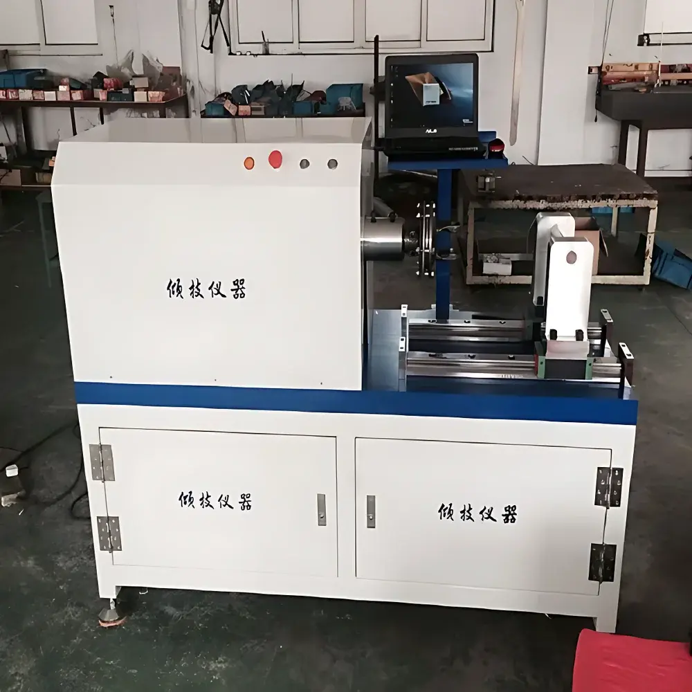
QJ21NZ Automotive Transmission Torsion Testing Machine
| Origin | Shanghai, China |
|---|---|
| Manufacturer Type | Authorized Distributor |
| Max Torque | 10,000 N·m |
| Torque Measurement Range | 50–5,000 N·m |
| Torque Resolution | ±0.001° (angular) |
| Torsion Angle Range | 0 to ±100,000° (4-digit digital display) |
| Motor Power | 1.5 kW |
| Torque Measurement Accuracy | ±0.5% FS |
| Torsion Angle Accuracy | ±0.5% FS |
| Angular Resolution | 0.001° |
| Torsion Speed Range | 0.01–1,000 °/min (infinitely variable) |
| Gauge Length | 1,500 mm |
| Specimen Clamping Diameter | Φ8–Φ40 mm (expandable) |
| Dimensions (L×W×H) | 2800 × 4700 × 1250 mm |
| Weight | 1,500 kg |
| Compliance | GB/T 9370–1999, JJG 269–1981, GB/T 239–1999 |
Overview
The QJ21NZ Automotive Transmission Torsion Testing Machine is a high-capacity, precision-engineered electromechanical system designed for static and quasi-static torsional characterization of automotive powertrain components—primarily manual and automatic transmission assemblies, drive shafts, gearboxes, and coupling systems. It operates on the principle of controlled angular displacement under applied torque, enabling direct measurement of torsional stiffness, yield torque, ultimate torsional strength, plastic deformation behavior, and hysteresis characteristics. The machine employs a closed-loop servo control architecture with a high-torque AC servo motor (1.5 kW), coupled to a precision planetary gearbox and a high-rigidity load frame. Its dual-sensor architecture integrates a calibrated torque transducer (rated up to 10,000 N·m) and an optical encoder-based angular position feedback system, ensuring traceable, repeatable, and metrologically sound torsion testing per national and international mechanical testing standards.
Key Features
- High-torque capacity (10,000 N·m maximum) with extended low-end sensitivity (50 N·m minimum measurable torque), supporting full-scale evaluation of heavy-duty transmission modules.
- Infinitely variable torsion speed control (0.01–1,000 °/min), enabling compliance with slow-rate creep tests, rapid failure analysis, and stepwise torque ramp protocols.
- Angular resolution of 0.001° and torsion angle accuracy of ±0.5% FS over a ±100,000° range—sufficient for multi-turn fatigue pre-conditioning and full-rotation functional validation.
- Rigid C-frame construction with 1,500 mm adjustable gauge length and self-centering hydraulic or mechanical clamping fixtures (Φ8–Φ40 mm standard; custom adapters available).
- Integrated real-time data acquisition at ≥1 kHz sampling rate, synchronized torque-angle-time logging with timestamped metadata.
- Compliance-ready hardware architecture: torque transducer calibrated to JJG 269–1981; angular encoder traceable to national angular metrology standards; mechanical design aligned with GB/T 9370–1999 and GB/T 239–1999 requirements.
Sample Compatibility & Compliance
The QJ21NZ accommodates assembled transmission units, differential housings, input/output shafts, synchronizer hubs, and modular gear train subassemblies. Its open-access test zone and modular fixture interface support both bench-mounted component-level testing and near-production-line integration. All torque and angular measurements meet the metrological requirements of ISO 7500-1 (Class 1), ASTM E143 (shear modulus determination), and ISO 527-2 (tensile properties of plastics—adapted for torsional analogs). When configured with optional micro-angle measurement accessories, it supports calculation of shear modulus (G) and non-proportional torque limits in accordance with GB/T 10128 (metallic materials—torsion testing). System documentation includes calibration certificates, uncertainty budgets, and verification reports compliant with GLP and internal QA audit frameworks.
Software & Data Management
The embedded control software utilizes virtual instrument architecture (LabVIEW-based runtime environment) to deliver deterministic real-time control, synchronized multi-channel acquisition, and automated test sequencing. Functions include programmable torque ramps, hold steps, cyclic loading profiles (±θ, ±T, or mixed-mode), and conditional termination triggers (e.g., torque drop >5%, angle deviation >0.1°). Raw data exports to CSV, Excel, and universal HDF5 formats. Report generation complies with ISO/IEC 17025 documentation requirements—each test record includes operator ID, environmental conditions (optional sensor inputs), calibration status flags, and digital signatures. Audit trail functionality meets FDA 21 CFR Part 11 criteria when deployed on validated Windows OS platforms with user role management.
Applications
- Validation of torque transfer efficiency and backlash behavior in planetary gear sets and synchronizer mechanisms.
- Quantification of torsional stiffness degradation during thermal cycling or lubricant aging studies.
- Failure mode analysis of clutch housing welds, bearing retainer deformation, and spline wear under sustained torsional load.
- Verification of OEM design specifications for shift-by-wire actuator torque output and hysteresis.
- Support for IATF 16949 process validation, PPAP submission packages, and durability test correlation with CAE models (e.g., Abaqus torsional boundary condition mapping).
- Research-grade characterization of novel composite transmission casings and lightweight alloy shafts under combined torsional-bending loads (with optional accessory kits).
FAQ
What standards does the QJ21NZ comply with for torque calibration and test methodology?
It conforms to GB/T 9370–1999 (torsion testing machines), JJG 269–1981 (torque measuring instruments), and GB/T 239–1999 (torsion testing methods for metallic materials), with traceability to national metrology institutes.
Can the system be integrated into an existing factory MES or LIMS environment?
Yes—via OPC UA or Modbus TCP protocol interfaces; API documentation and driver packages are provided for seamless SCADA and quality data platform integration.
Is torsional elastic modulus (G) calculation supported out-of-the-box?
When equipped with the optional high-resolution angular displacement sensor kit and calibrated specimen geometry input, the software computes G using the standard formula G = (T × L) / (J × θ), with uncertainty propagation per GUM guidelines.
What maintenance intervals and consumables are recommended?
Servo motor and gearbox oil replacement every 5,000 operational hours; torque transducer recalibration annually or after 10,000 test cycles; clamping jaw inserts replaced per wear inspection (typically every 500–1,000 tests depending on material hardness).
Related Products


