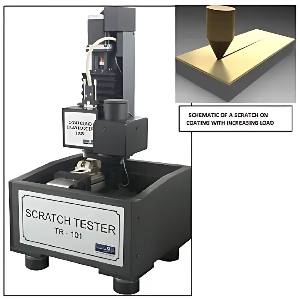
Ducom TR-101 Advanced Nano/Micro Scratch Tester
| Brand | Ducom |
|---|---|
| Origin | USA |
| Model | TR-101 |
| Instrument Type | (Micro/Nano) Scratch Tester |
| Maximum Indentation Depth | 5 mm |
| Effective Normal Load Range | 10 mN – 200 N |
| Load Resolution | 1 µN |
| Displacement Range | 0.1 mm – 50 mm |
| Displacement Resolution | 1 µm |
| Maximum Friction Force | 200 N |
| Indenter Tip | Rockwell C Diamond Tip |
Overview
The Ducom TR-101 Advanced Nano/Micro Scratch Tester is a computer-controlled, high-precision tribomechanical characterization system engineered for quantitative evaluation of thin-film adhesion, scratch resistance, interfacial cohesion, and progressive failure mechanisms under controlled normal and tangential loading. Operating on the principle of quasi-static progressive loading combined with real-time multi-signal acquisition (normal force Fn, tangential friction force Ft, acoustic emission AE, and vertical displacement z), the TR-101 enables deterministic mapping of critical transition events—including elastic deformation, plastic yielding, coating fracture, delamination onset, and substrate penetration—across a broad mechanical spectrum (10 mN to 200 N). Its servo-regulated normal load actuation ensures sub-micron force stability even on topographically non-planar surfaces, while synchronized optical imaging and profilometric post-analysis provide spatially registered mechanical–morphological correlation essential for ISO 20502, ASTM D7027, and ISO 23987-compliant surface engineering validation.
Key Features
- High-resolution dual-axis force measurement: Fn (10 mN–200 N, resolution 1 µN) and Ft (up to 200 N) acquired at ≥1 kHz sampling rate
- Motorized XYZ stage with programmable translation (0.1–50 mm range, 1 µm resolution) and repeatable positioning accuracy ≤±0.5 µm
- Rockwell C geometry diamond indenter (120° apex angle, 200 µm tip radius) certified per ISO 6508-1 for standardized hardness-correlated scratch initiation
- Integrated acoustic emission sensor (100 kHz–1 MHz bandwidth) for real-time detection of brittle fracture, interfacial decohesion, and micro-crack nucleation
- Automated optical imaging module with motorized zoom lens (20×–200× magnification), LED ring illumination, and stitching algorithm for full-scratch-length panoramic reconstruction
- Profilometry-capable Z-axis transducer enabling pre- and post-scan surface topography acquisition at ≤0.5 nm vertical resolution (using low-load (<1 mN) contact mode)
Sample Compatibility & Compliance
The TR-101 accommodates rigid substrates up to 150 mm × 150 mm × 50 mm (L×W×H) and supports flat, slightly curved (R ≥ 50 mm), or polished cross-sectioned specimens. It is routinely deployed for characterization of PVD/CVD coatings (e.g., TiN, CrN, DLC), thermal spray deposits (WC-Co, Al2O3), polymer films (PTFE, epoxy, acrylic), and diffusion-treated surfaces (nitrided steel, carburized alloys). All test protocols comply with international standards including ISO 20502 (coating adhesion by scratch testing), ASTM D7027 (scratch resistance of organic coatings), ISO 23987 (nano/micro-scratch testing of hard coatings), and support GLP/GMP audit readiness through timestamped, user-authenticated data logs and electronic signature-capable reporting.
Software & Data Management
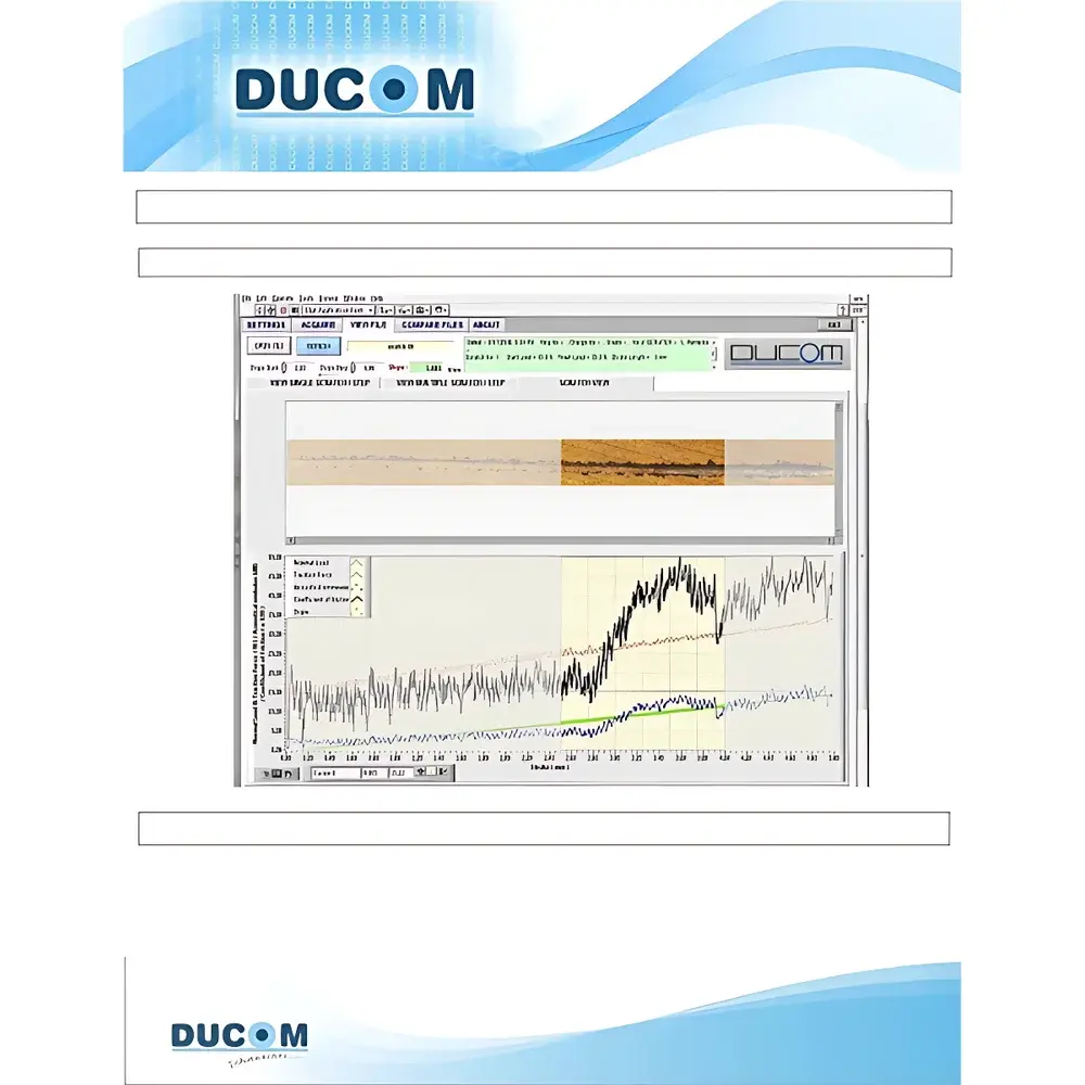
TR-101 operates via Ducom’s proprietary ScratchTest™ v4.2 software—a Windows-based platform supporting fully parametric test definition, real-time multi-channel visualization (Fn, Ft, R = Ft/Fn, AE RMS, z), and synchronized image–curve navigation. Users define scratch profiles using seven independent parameters: start/end normal load, load profile (constant, linear ramp, or stepwise), scratch length, velocity (0.1–20 mm/min), inter-track spacing, number of passes, and unidirectional/bidirectional motion. Post-test, the software automatically stitches >50 high-magnification images into a seamless composite scan; each pixel is georeferenced to its corresponding coordinate on the force–displacement curve. Export options include CSV (for MATLAB/Python analysis), PDF reports with embedded metadata (operator ID, calibration traceability, environmental conditions), and FDA 21 CFR Part 11–compliant audit trails with immutable event logging.
Applications
- Determination of critical load (Lc) for brittle ceramic coatings (TiN, Al2O3, SiC) via AE burst onset and sudden Ft deviation
- Quantification of functional load limits in low-friction polymer coatings (PTFE, UHMWPE) under progressive shear stress
- Optimization of nitriding time/temperature parameters by correlating Lc with case depth measured via microhardness profiling
- Interfacial toughness estimation using energy-based models (e.g., ∫(Ft·dx) during delamination propagation)
- Routine QC screening of batch-to-batch coating uniformity, adhesion consistency, and defect sensitivity in aerospace and medical device manufacturing
FAQ
What types of indenters are supported beyond the standard Rockwell C diamond tip?
The TR-101 accepts interchangeable conical, spherical, and Berkovich tips (diameters 1–50 µm) via its modular holder; tip exchange requires recalibration using NIST-traceable reference samples.
Can the system perform combined nanoindentation and scratch tests in a single setup?
Yes—by switching to the optional nanoindenter module (with 10 mN max load, 0.1 nN resolution), users conduct sequential indentation–scratch sequences on identical locations for structure–property linkage.
Is the software validated for regulated environments (e.g., ISO 13485 or ICH Q5E)?
ScratchTest™ v4.2 includes IQ/OQ documentation templates, electronic signature workflows, and configurable audit trail export compliant with FDA 21 CFR Part 11 and EU Annex 11 requirements.
How is lateral force calibration performed and how often is it required?
Lateral force sensors are calibrated biannually using traceable dead-weight standards; automated daily verification routines confirm linearity and hysteresis within ±0.5% of full scale.
Does the system support environmental control (e.g., humidity or temperature chambers)?
Yes—the base platform integrates with third-party environmental stages (−40°C to +200°C, 10–95% RH) via standardized mounting interfaces and synchronized data acquisition triggers.


