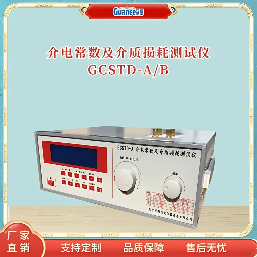
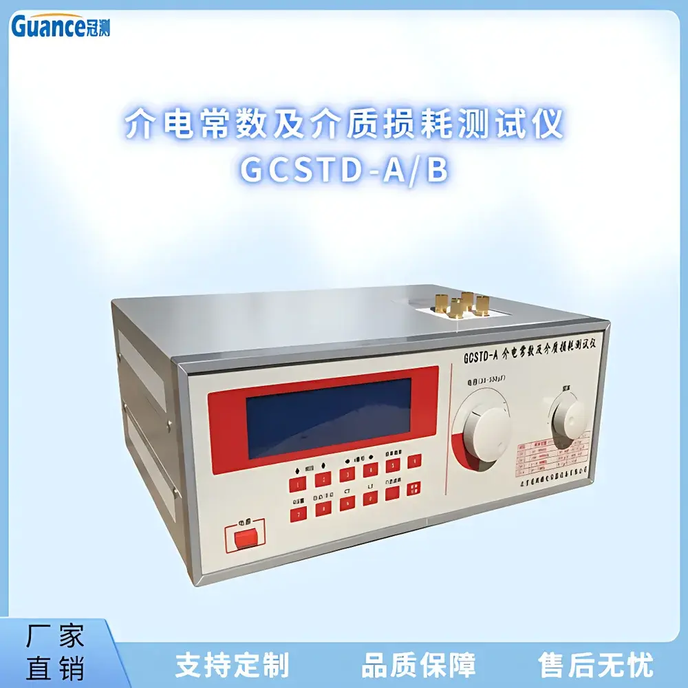
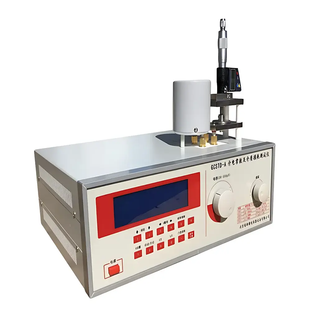
GuanCe GCSTD-A/B High-Frequency Dielectric Constant and Dissipation Factor Analyzer
| Brand | GuanCe Instruments |
|---|---|
| Origin | Beijing, China |
| Manufacturer Type | Authorized Distributor |
| Region of Manufacture | Domestic (China) |
| Model | GCSTD-A/B |
| Price | USD 1,400 (approx.) |
| Measurement Principle | Resonant Frequency Method (Q-meter based) |
| Frequency Range | Selectable across three variants (A/B/C — model-specific bands, typically 1 MHz to 100 MHz) |
| Sample Types | Solid, Liquid, Powder |
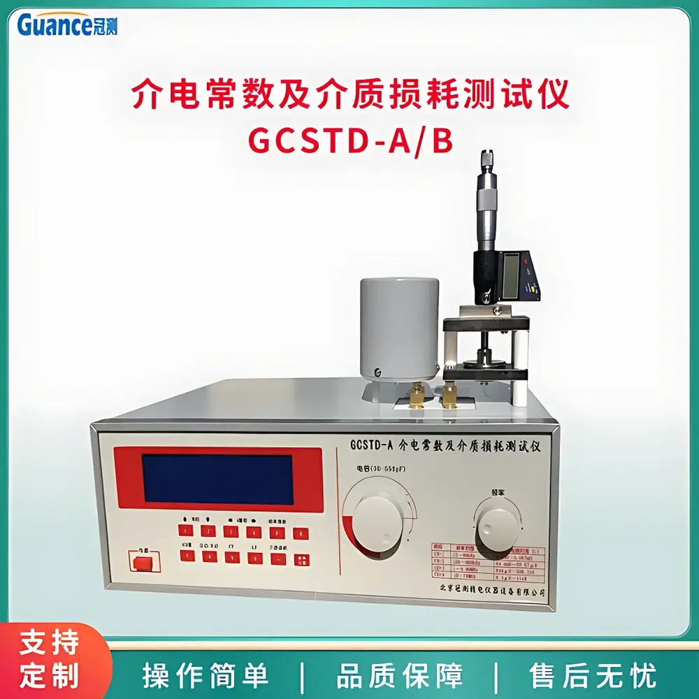
| Electrode Diameter | 38 mm (standard) |
| Solid Sample Thickness Range | 0.5–15 mm |
| Liquid Cell Dimensions | ID 48 mm × Depth 7 mm (optional) |
| Operating Temperature | 0–40 °C |
| Relative Humidity | <80% RH |
| Power Supply | 220 V ±10%, 50 Hz ±2.5 Hz |
| Power Consumption | ~25 W |
| Net Weight | ~7 kg |
| Dimensions (L×W×H) | 380 × 280 × 132 mm |
Overview
The GuanCe GCSTD-A/B High-Frequency Dielectric Constant and Dissipation Factor Analyzer is a precision impedance measurement system engineered for the quantitative characterization of dielectric properties in non-metallic materials under high-frequency alternating electric fields. It operates on the resonant frequency method—a well-established technique rooted in Q-meter architecture—wherein the sample forms part of a tunable LC resonator. By precisely measuring shifts in resonant frequency and bandwidth (or Q-factor), the instrument calculates complex permittivity (ε* = ε′ − jε″), from which the real part (dielectric constant, ε′) and loss tangent (tan δ = ε″/ε′) are derived. Designed for rigorous laboratory use, the GCSTD-A/B supports standardized evaluation of insulating ceramics, polymer composites, rubber formulations, electronic structural ceramics, and liquid dielectrics—enabling researchers and quality engineers to correlate microstructural features (e.g., porosity, crystallinity, filler dispersion) with macroscopic electromagnetic response.
Key Features
- Microcontroller-based digital control system with automatic resonance search and frequency locking for stable, repeatable measurements.
- Multi-range Q-value auto-scaling and dynamic amplitude stabilization to minimize signal distortion and thermal drift effects.
- Low-residual-inductance tuning circuitry optimized for minimal parasitic contributions—critical for accurate tan δ determination at elevated frequencies.
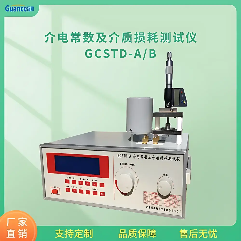
- Standardized electrode configuration: 38 mm diameter parallel-plate electrodes compatible with solid discs (thickness 0.5–15 mm), optional liquid cells (48 mm ID × 7 mm depth), and powder-compaction fixtures.
- Nine calibrated reference inductors included for broad impedance coverage and cross-validation across material types and frequency bands.
- Integrated digital display with direct readout of ε′, tan δ, C (capacitance), L (inductance), Q, and series/parallel resistance values.
Sample Compatibility & Compliance
The GCSTD-A/B accommodates solid dielectrics (ceramics, plastics, elastomers), low-conductivity liquids (transformer oils, silicone fluids), and compacted powders—provided samples meet dimensional and homogeneity requirements. Its measurement methodology aligns with internationally recognized standards including ASTM D150 and IEC 60250 for solid insulators; GB/T 1409–2006, GB/T 5654–2007, GB/T 21216–2007, GB/T 1693–2007, and GB/T 5594.4–1985 for Chinese national compliance. While not inherently 21 CFR Part 11 compliant (as it lacks audit-trail software), raw measurement data can be manually recorded in GLP/GMP-aligned lab notebooks or exported via external logging systems for traceability in regulated R&D environments.
Software & Data Management
The GCSTD-A/B is a standalone hardware platform without embedded PC connectivity or proprietary software. All operations—including frequency selection, resonance tuning, and parameter readout—are executed locally via front-panel controls and LED/LCD display. For documentation purposes, users may record results manually or integrate the instrument into automated test benches using analog voltage outputs (if externally enabled) or digital TTL triggers (subject to optional firmware upgrade). Data integrity relies on operator adherence to standardized test protocols defined in referenced ASTM and GB documents. No cloud storage, remote access, or database synchronization is supported.
Applications
- Development and qualification of high-frequency substrate materials for PCBs and RF packaging.
- Quality control of ceramic capacitors, piezoelectric elements, and insulating bushings.
- Characterization of polymer matrix composites used in aerospace radomes and antenna housings.
- Evaluation of aging effects in transformer oils and cable insulation fluids per IEC 60422.
- Research into structure–property relationships in ferroelectric and relaxor dielectrics.
- Validation of dielectric performance in biomedical polymers exposed to RF energy (e.g., MRI-compatible devices).
FAQ
What frequency ranges do the GCSTD-A and GCSTD-B models support?
The GCSTD-A and GCSTD-B differ primarily in their factory-set oscillation bandwidths—typically covering discrete segments within 1 MHz to 100 MHz. Exact upper/lower limits depend on internal oscillator design and matching network calibration; users must select the variant aligned with their target application frequency (e.g., 1–10 MHz for power electronics, 30–80 MHz for RF ceramics).
Can the instrument measure conductive or semi-crystalline polymers?
It is intended for low-loss, low-conductivity dielectrics. Materials with DC conductivity >10⁻⁶ S/m or significant ionic mobility may yield unstable resonance or non-linear tan δ responses—requiring validation against reference standards prior to routine use.
Is calibration traceable to national metrology institutes?
The instrument includes factory calibration using NIST-traceable LC standards; however, end-user recalibration requires certified passive components and a metrology-grade impedance analyzer (e.g., Keysight E4990A) for full uncertainty budgeting.
Does it support temperature-controlled measurements?
No built-in environmental chamber interface is provided. For variable-temperature studies, users must integrate external heated/cooled sample stages with mechanical alignment compatibility and electrical feedthroughs rated for RF frequencies.
How is electrode contact resistance minimized during solid-sample testing?
The standard fixture applies controlled mechanical pressure (via spring-loaded or screw-adjusted platens) and uses gold-plated electrodes to reduce interfacial impedance. Surface flatness (≤1 µm roughness) and absence of air gaps are prerequisites for valid ε′ extraction.


