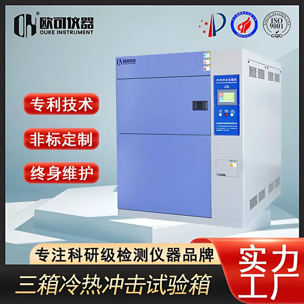
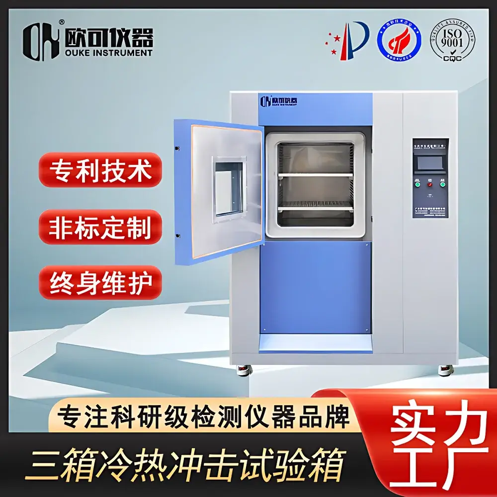
OK-TS-49.888 Thermal Shock Test Chamber
| Brand | OK Instruments |
|---|---|
| Origin | Guangdong, China |
| Manufacturer Type | Direct Manufacturer |
| Model | OK-TS-49.888 |
| High Temperature Range | +150 °C |
| Low Temperature Range | −50 °C |
| Thermal Shock Range | −50 °C to +150 °C |
| Temperature Stability | ±2 °C |
| Transition Time (Hot ↔ Cold) | ≤10 s |
| Heating/Cooling Rate (Chamber Air) | 20 °C/min (typical, per IEC 60068-2-14 definition) |
Overview
The OK-TS-49.888 Thermal Shock Test Chamber is an engineered environmental test system designed to subject electronic components, automotive modules, aerospace assemblies, and advanced packaging materials to rapid, repetitive thermal transitions between extreme high- and low-temperature environments. Unlike temperature cycling or rapid temperature change chambers—which impose gradual, linear thermal stress—the OK-TS-49.888 delivers true thermal shock via discrete, stepwise temperature exposure. Its operational principle adheres strictly to the physical definition of thermal shock: a sudden, discontinuous shift in ambient temperature experienced by a test specimen, inducing transient thermal gradients that drive mechanical strain due to differential expansion coefficients across material interfaces.
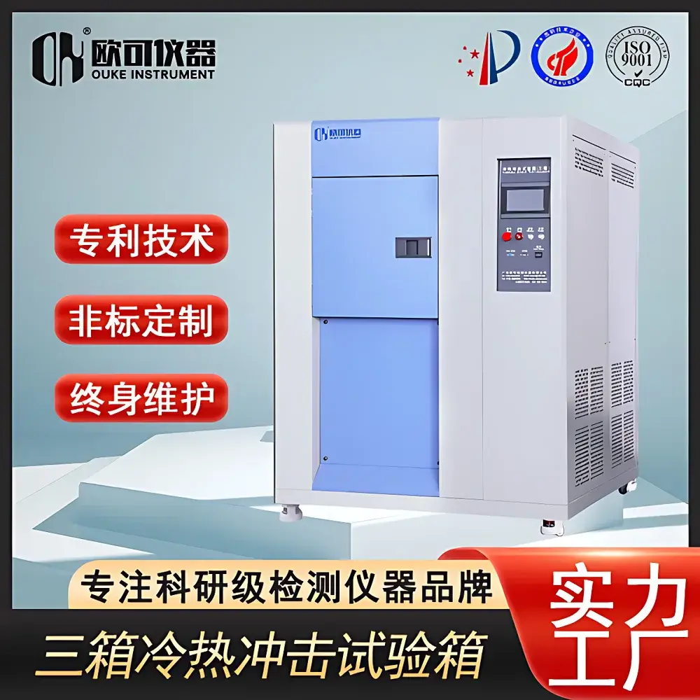
This chamber implements a dual-chamber (two-box) configuration with pneumatically actuated specimen transfer. A motorized lift basket moves the test load between a thermally stabilized hot zone (+150 °C) and a cryogenic cold zone (−50 °C), achieving inter-zone transition in ≤10 seconds—fully compliant with the timing requirements specified in IEC 60068-2-14, MIL-STD-883 Method 1010.8, and JESD22-A104D. The resulting thermal transients expose latent defects such as solder joint microcracks, die attach delamination, wire bond lift-off, hermetic seal failure, and PCB layer separation—failure modes not detectable under steady-state or ramped thermal conditions.
Key Features
- Dual-zone architecture with independent PID-controlled heating and refrigeration systems for simultaneous maintenance of extreme setpoints (−50 °C and +150 °C)
- Pneumatic lift basket mechanism enabling ≤10-second specimen transfer—validated per IEC 60068-2-14 Annex A
- Temperature stability maintained at ±2 °C across both zones during dwell periods, ensuring reproducible thermal boundary conditions
- Stainless-steel interior construction with insulated double-wall panels and silicone-sealed access doors for minimal thermal leakage
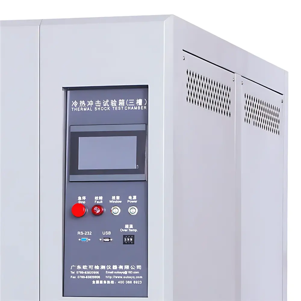
- Integrated safety interlocks including over-temperature cut-off, door-open freeze protection, and refrigerant pressure monitoring
- Programmable controller supporting up to 999 cycles, multi-segment dwell/transfer sequences, and user-defined recovery time windows
Sample Compatibility & Compliance
The OK-TS-49.888 accommodates specimens up to standard industrial rack-mount dimensions and supports static electrical biasing during transit via optional feedthrough connectors. Its mechanical transfer design is optimized for rigid, medium-mass samples (e.g., PCBAs, sensors, power modules, and optoelectronic housings) that tolerate controlled inertial loading during basket motion. It is not intended for fragile, unmounted wafers or fluid-filled devices requiring zero-vibration handling—applications better served by three-box (air-switching) configurations.
Compliance is built into the test methodology: the chamber’s transition time, dwell stability, and temperature uniformity profiles are validated against IEC 60068-2-14 (identical to GB/T 2423.22), MIL-STD-883H, and JEDEC JESD22-A104D. Calibration traceability follows ISO/IEC 17025 protocols, with annual verification performed using NIST-traceable PT100 probes placed at designated test volume locations. All test logs include timestamped temperature histories for audit readiness under GLP and GMP frameworks.
Software & Data Management
Equipped with OK’s proprietary TSC-View™ control interface, the chamber provides real-time graphical monitoring of chamber air temperatures, basket position status, cycle count, and elapsed test time. Data logging records temperature readings at 1 Hz resolution across all critical zones and exports CSV files compatible with MATLAB, JMP, and Minitab for statistical process analysis. Optional Ethernet/IP connectivity enables integration into centralized test management platforms (e.g., QMS or MES systems) and supports FDA 21 CFR Part 11-compliant electronic signatures and audit trails when deployed with validated software versioning and role-based access controls.
Applications
- Qualification testing of automotive ECUs per AEC-Q200 Rev D thermal shock requirements
- Reliability screening of semiconductor packages (QFN, BGA, CSP) prior to burn-in
- Validation of adhesive bonds and conformal coatings under thermal mismatch stress
- Failure analysis support for root-cause investigation of field returns linked to thermal cycling fatigue
- Pre-compliance verification for MIL-STD-810H Method 503.5 (Temperature Shock) and DO-160G Section 4.9
FAQ
What distinguishes thermal shock testing from temperature cycling?
Thermal shock applies instantaneous, step-function temperature changes between two stable extremes, inducing mechanical fracture mechanisms. Temperature cycling uses continuous, linear ramps to simulate long-term thermal fatigue—governed by different standards (e.g., IEC 60068-2-11 vs. IEC 60068-2-14).
Is this chamber suitable for powered-in testing?
Yes—optional electrical feedthroughs (up to 10 channels, 300 VAC/5 A) allow real-time functional monitoring during transfer; however, dynamic electrical connection requires custom fixturing to accommodate basket motion.
Does it meet MIL-STD-883H requirements?
Yes—the ≤10 s transition time, ±2 °C stability, and programmable dwell durations satisfy Method 1010.8. Full compliance documentation, including calibration certificates and uncertainty budgets, is provided with each unit.
Can liquid nitrogen be integrated for faster cooling?
Not natively supported; the OK-TS-49.888 relies on cascade mechanical refrigeration for −50 °C operation. LN₂ retrofitting would require structural modification and voids factory warranty and compliance certification.
How is temperature uniformity verified across the test volume?
Per IEC 60068-2-14, nine-point mapping is performed using calibrated PT100 sensors at defined spatial coordinates; uniformity must remain within ±2 °C during dwell phases. This validation is repeated annually or after major maintenance.


