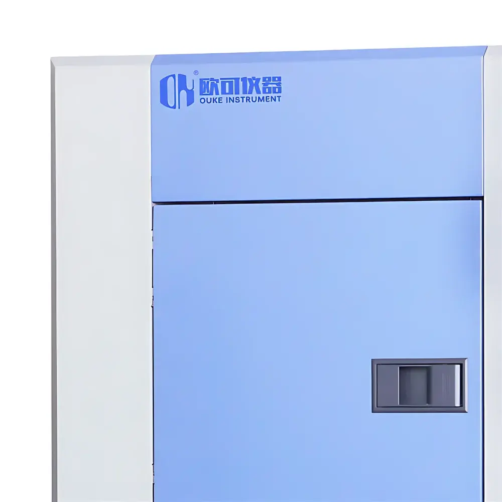
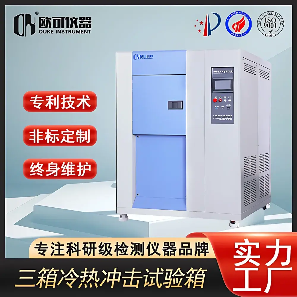
OK-TS-10 Three-Zone Thermal Shock Test Chamber
| Brand | OK Instruments |
|---|---|
| Origin | Guangdong, China |
| Manufacturer Type | Direct Manufacturer |
| Model | OK-TS-10 |
| Price | USD 11,200 (FOB) |
| High-Temperature Range | +150 °C |
| Low-Temperature Range | −50 °C |
| Thermal Shock Range | −50 °C to +150 °C |
| Temperature Stability | ±2 °C |
| Heating Rate | 10 °C/min |
| Cooling Rate | 10 °C/min |
Overview
The OK-TS-10 Three-Zone Thermal Shock Test Chamber is an engineered solution for accelerated thermal stress evaluation of electronic components, automotive modules, aerospace hardware, and high-reliability assemblies. Unlike two-chamber systems that physically shuttle test specimens between hot and cold zones—introducing mechanical vibration, positional uncertainty, and extended recovery times—the OK-TS-10 employs a stationary sample architecture. It maintains independent, continuously conditioned high-temperature (+150 °C) and low-temperature (−50 °C) reservoirs, while the test specimen remains fixed in a thermally isolated central chamber. Rapid thermal transitions are achieved via pneumatically actuated airflow valves that direct pre-conditioned air from either reservoir into the test zone within ≤3 seconds. This design conforms to the physical principle of convective thermal shock delivery as defined in IEC 60068-2-14, where environmental temperature transition—not specimen temperature—is the controlled variable. The system is calibrated for uniformity, stability, and repeatability across its full operational envelope, supporting qualification testing under GLP-compliant workflows.
Key Features
- Three-zone architecture: independent high-temp chamber, low-temp chamber, and static test chamber—eliminating mechanical handling of samples
- Thermally optimized airflow path with stainless-steel ducting and high-efficiency centrifugal blowers for rapid thermal transfer
- Pneumatic valve system with <1.5 s actuation time, ensuring reproducible transition intervals per IEC 60068-2-14 Clause 6.2
- Dual-stage refrigeration circuit with cascade cooling capability for stable −50 °C operation without cryogenic consumables
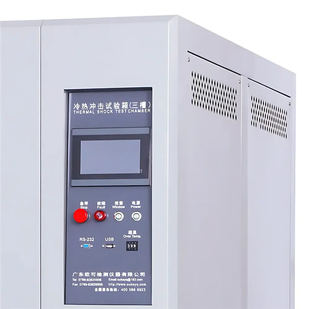
- Programmable controller with 100-segment ramp-soak profiles, real-time deviation monitoring, and alarm-triggered data freeze
- Test chamber interior constructed from SUS304 stainless steel with rounded corners and non-reflective matte finish to minimize thermal stratification
- Integrated dew point monitoring and automatic defrost cycle confined exclusively to the low-temperature reservoir—no frost accumulation in the test zone
Sample Compatibility & Compliance
The OK-TS-10 accommodates samples up to 450 mm × 450 mm × 450 mm (W×D×H) with a maximum load capacity of 30 kg. Its static mounting configuration supports devices with external cabling, optical feeds, or pneumatic interfaces via three dedicated feedthrough ports (Φ25 mm, sealed with silicone grommets). The chamber meets thermal performance criteria specified in IEC 60068-2-14 (Change of Temperature), GJB 150.5A-2009 (Environmental Test Methods for Military Equipment), and JESD22-A104F (Temperature Cycling for Integrated Circuits). Optional validation packages include IQ/OQ documentation aligned with ISO/IEC 17025 requirements and traceable NIST-calibrated sensor sets for audit-ready compliance.
Software & Data Management
Equipped with OK-TCM v3.2 control software, the system provides full-cycle data logging at 1 Hz resolution—including chamber air temperature, valve status, compressor discharge pressure, and setpoint deviation. All records are timestamped, digitally signed, and stored in encrypted CSV and PDF formats compliant with FDA 21 CFR Part 11 Annex 11 requirements. Audit trails capture user login/logout events, parameter modifications, and manual override actions. Remote access is supported via TLS 1.2-secured Ethernet connection; no cloud dependency or third-party telemetry is enabled by default. Data export supports automated FTP push to internal LIMS or MES platforms.
Applications
- Automotive electronics: ECU housings, ADAS sensors, battery management systems (BMS), and infotainment modules subjected to thermal cycling per ISO 16750-4
- Aerospace components: Avionics enclosures, flight control actuators, and satellite payload interfaces tested against DO-160 Section 4.6
- Semiconductor packaging: QFN, BGA, and SiP assemblies evaluated for interfacial delamination risk using JEDEC J-STD-020D reflow simulation protocols
- Medical device PCBs: Class II and III electronics requiring thermal robustness validation per IEC 60601-1 Clause 11.3
- New energy systems: EV traction inverters, DC-DC converters, and charging port assemblies validated under GB/T 31467.3 thermal shock conditions
FAQ
What distinguishes the three-zone architecture from conventional two-chamber thermal shock testers?
The OK-TS-10 eliminates sample movement entirely—replacing mechanical transfer arms with precision airflow routing. This removes vibration-induced failure modes, improves test repeatability, and enables continuous electrical monitoring during transitions.
Does the system support automated test sequencing per IEC 60068-2-14 Method Na?
Yes. Predefined cycles—including dwell time, transition duration, and number of cycles—are programmable via the onboard controller or OK-TCM software. Transition time is measured as the interval between 90% of upper and lower temperature thresholds in the test chamber air, not the specimen.
How is temperature uniformity verified across the test volume?
Uniformity is validated per IEC 60068-3-5 using nine calibrated PT100 sensors arranged in a 3×3 vertical grid. Typical results show ±1.2 °C deviation at steady state within the usable test volume.
Can the chamber be integrated into an existing factory automation network?
Yes. Modbus TCP and RS-485 interfaces are standard. Digital I/O terminals support start/stop commands, fault signaling, and cycle completion triggers compatible with PLC-based MES environments.
What maintenance intervals are recommended for long-term calibration stability?
Sensor verification every 6 months, refrigerant oil analysis annually, and full airflow path inspection—including valve seals and blower impeller balance—every 18 months. OK Instruments provides certified field service engineers for on-site recalibration.


