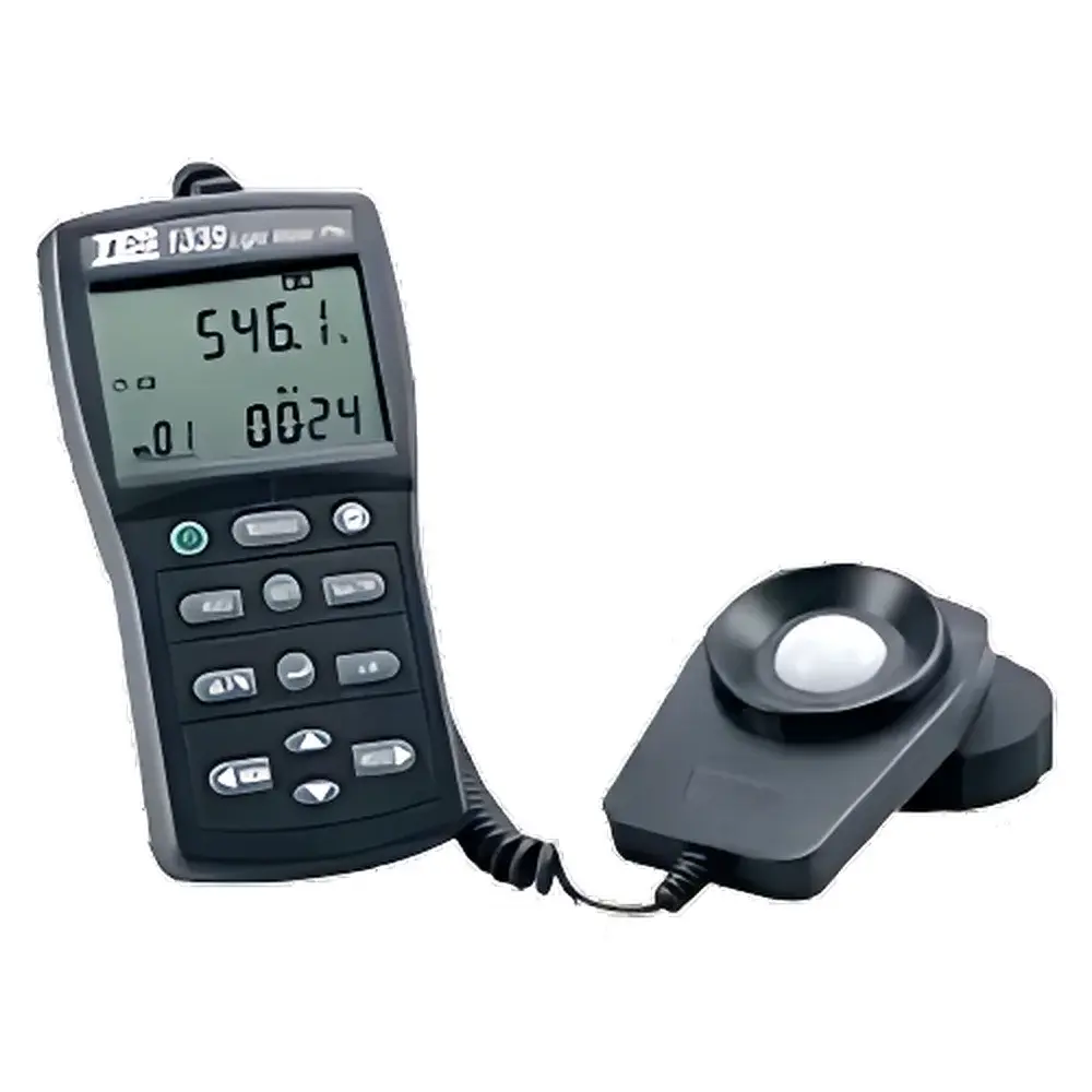
TES TES-1339 Advanced Illuminance Meter
| Brand | TES |
|---|---|
| Origin | Taiwan |
| Model | TES-1339 |
| Measurement Range | 0.01–999,900 Lux (5 auto-ranging scales) |
| Resolution | 0.01 Lux / 0.001 fc |
| Accuracy | ±3% of reading ±5 digits (calibrated at 2856 K standard incandescent source) |
| Response Time | ~5 readings/sec |
| Photodetector | Silicon photodiode with cosine-corrected diffuser |
| Memory Capacity | 50 data sets |
| Operating Temp | 0–50°C, <80% RH |
| Power | 6× AAA batteries (~100 h life) |
| Sensor Cable Length | 150 cm |
| Dimensions (Meter) | 150 × 72 × 33 mm |
| Weight | ~250 g |
| Compliance | CNS 5119 Class II |
Overview
The TES TES-1339 Advanced Illuminance Meter is a precision optical measurement instrument engineered for high-fidelity photometric evaluation in laboratory, industrial, architectural lighting, and quality assurance environments. Based on the fundamental principle of photopic luminous flux detection, it employs a calibrated silicon photodiode sensor with a cosine-corrected diffuser to accurately convert incident visible light (380–780 nm) into electrical signal proportional to illuminance—weighted by the CIE standard photopic luminosity function V(λ). Its design adheres to the metrological requirements of CNS 5119 Class II, ensuring traceable performance under ambient conditions typical of indoor lighting validation, workplace safety compliance (e.g., IEC 62471, EN 12464-1), and daylight harvesting system commissioning. The instrument delivers stable, repeatable measurements across five auto-ranging decades—from ultra-low ambient levels (0.01 Lux) to intense artificial or solar irradiance (up to 999,900 Lux), with real-time compensation for temperature drift (±0.1%/°C) and spectral mismatch (f’₁ ≤ 6%).
Key Features
- High-resolution dual-display LCD showing simultaneous primary reading and secondary parameter (e.g., average, deviation, or STRAY+LIGHT mode)
- True integrating measurement capability for time-weighted illuminance (lux·s), supporting energy-based lighting analysis per ISO/CIE guidelines
- Stray-light rejection algorithm enabling accurate source-specific illuminance assessment in multi-source or reflective environments
- Configurable averaging (point average over user-defined intervals) and time-lock functions for transient light stability evaluation
- Integrated comparator mode for pass/fail threshold verification against predefined upper/lower limits
- Auto-hold and manual hold functions with visual indicator for stabilized readings during field surveys
- Programmable data logging (50 memory slots) with on-device recall—no external software required for basic audit trail
- Automatic power-off after 15 minutes of inactivity; low-battery indicator ensures uninterrupted calibration integrity
Sample Compatibility & Compliance
The TES-1339 is optimized for planar, diffuse, and directional visible-light sources including LED arrays, fluorescent tubes, HID lamps, natural daylight, and OLED panels. Its cosine-corrected sensor head (100 × 60 × 27 mm) maintains angular response within ±5% up to 75° incidence—critical for uniformity mapping per IES LM-79 and EN 13201-3. The device conforms to CNS 5119 Class II specifications for illuminance meters, which align closely with IEC 60825-1 (laser safety auxiliary measurement) and ISO/CIE 19476:2014 (photometric instrument classification). While not FDA 21 CFR Part 11–compliant out-of-the-box (as it lacks electronic signature and audit trail export), its measurement repeatability (≤0.5% RSD over 10 consecutive readings at 500 Lux) supports GLP-aligned documentation when used with controlled SOPs and manual logbook entries.
Software & Data Management
The TES-1339 operates as a standalone field instrument with embedded firmware—no proprietary PC software or driver installation is required. All 50 stored measurements are accessible directly via the front-panel interface using intuitive navigation keys. Each record includes timestamp-equivalent sequence index, measured value, range setting, and unit (Lux or fc). For integration into larger QA/QC workflows, users may manually transcribe values into LIMS-compatible spreadsheets or export via optional RS-232/USB adapters (sold separately). The meter’s fixed calibration architecture—performed at a certified 2856 K blackbody source—ensures long-term stability without field recalibration; however, periodic verification against NIST-traceable reference standards (e.g., Optronik OL 770) is recommended every 12 months per ISO/IEC 17025 guidance.
Applications
- Workplace lighting compliance audits per OSHA 1910.303 and EU Directive 2002/44/EC
- Photobiological safety assessments (IEC 62471) for LED lighting products
- Architectural daylight modeling validation and LEED EQ Credit 8.1 documentation
- Production line verification of backlight uniformity in display manufacturing
- Greenhouse PAR (Photosynthetically Active Radiation) proxy evaluation where lux-to-PPFD conversion factors are applied
- Educational photometry labs requiring robust, student-safe instrumentation with clear metrological traceability
FAQ
What is the spectral response accuracy of the TES-1339 relative to the CIE V(λ) curve?
The f’₁ spectral mismatch error is ≤6%, verified per CIE Publication 69 and aligned with Class II tolerances in CNS 5119.
Can the TES-1339 measure pulsed or modulated light sources (e.g., PWM-driven LEDs)?
Yes—its 5-Hz sampling rate and analog integration circuitry enable reliable RMS-equivalent illuminance capture for frequencies up to 200 Hz; for higher-frequency flicker analysis, a dedicated flickermeter (e.g., TES-1335) is recommended.
Is the sensor head detachable and replaceable?
The sensor is permanently integrated with a 150 cm shielded coaxial cable; replacement requires factory service due to calibration coupling.
Does the instrument support custom calibration for non-standard light sources?
No—factory calibration is fixed to 2856 K incandescent reference; users requiring source-specific correction must apply post-measurement correction factors based on published SPD data.
How is stray light rejection implemented physically and algorithmically?
A combination of baffled optical housing, spectral filtering, and real-time differential measurement between main and auxiliary photodiode channels enables STRAY+LIGHT mode operation.