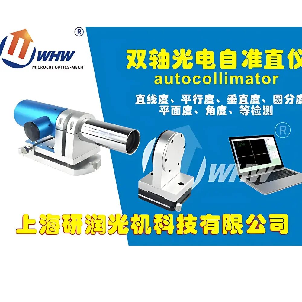
YANRUN MC030-YRMAT200/38/1 Dual-Axis Photoelectric Autocollimator
| Focal Length | 200 mm |
|---|---|
| Aperture | 38 mm |
| Light Source | Imported Semiconductor LED |
| Measurement Range | 0–10 m |
| Detector | High-Precision Photodiode Array |
| Display Resolution | Adjustable from 1″ to 0.0001″ (arc sec) |
| Field of View (X/Y) | 3200″ × 2400″ (arc sec) |
| Accuracy (Center, ±1000″) | ±1″ (arc sec) |
| Frequency Response | ≤30 Hz |
| Interface | USB 2.0 |
| Dimensions | 288 × 105 × 115 mm |
| Weight | 3.5 kg |
| Operating System | Windows 7 or later (64-bit) |
| Minimum CPU | Intel Core i3-4th Gen, 2.3 GHz |
Overview
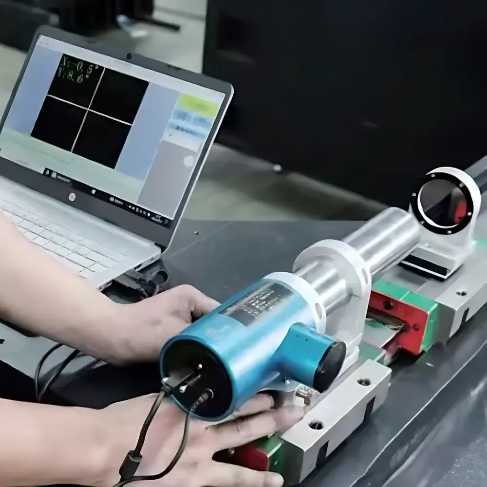
The YANRUN MC030-YRMAT200/38/1 Dual-Axis Photoelectric Autocollimator is a precision angular metrology instrument engineered for high-reproducibility measurement of minute angular deviations in two orthogonal axes (X and Y) simultaneously. It operates on the fundamental optical principle of autocollimation: a collimated beam—generated by projecting a reticle located at the focal plane of a 200 mm focal length objective lens—is reflected off a planar mirror and re-imaged onto a high-resolution photodiode array sensor positioned at the same focal plane. When the mirror rotates by angle α, the returned image shifts by ΔS = 2f·tan(2α) ≈ 4fα (for small angles), enabling sub-arcsecond angular quantification through pixel-level displacement analysis. This co-focal, non-contact method eliminates parallax and human sighting error inherent in traditional visual autocollimators, delivering traceable, digital angular data suitable for ISO/IEC 17025-compliant calibration laboratories and GMP-aligned production environments.
Key Features
- Dual-axis simultaneous measurement capability with independent X/Y coordinate tracking and real-time vector resolution.
- High-stability semiconductor LED light source with >50,000-hour service life and consistent spectral output—no warm-up drift or filament degradation.
- Adjustable display resolution down to 0.0001 arc second (0.005 µrad), configurable per application requirement without hardware modification.
- Integrated electronic eyepiece interface with live centroid detection algorithm, supporting automatic curve fitting, error envelope calculation, and deviation trend analysis.
- Compact monolithic housing (288 × 105 × 115 mm, 3.5 kg) optimized for portable deployment in cleanrooms, machine tool shops, and field metrology setups.
- USB 2.0 interface with deterministic latency (<10 ms) and plug-and-play compatibility with Windows 7+ (64-bit); driver-free operation under standard HID protocols.
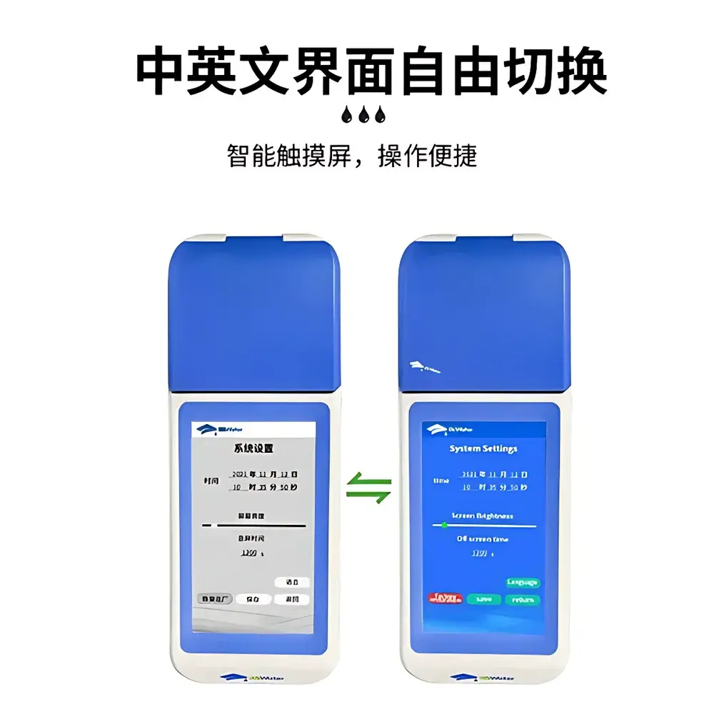
- Multi-language UI support (English, Chinese, Russian, Korean) with context-sensitive tooltips and standardized terminology aligned with ISO 10110 and VDI/VDE 2617 guidelines.
Sample Compatibility & Compliance
The MC030-YRMAT200/38/1 is compatible with standard optical flats (λ/20 surface accuracy), kinematic mirror mounts, and custom retroreflector targets used in alignment of CNC machine tool spindles, laser interferometer bases, and optical breadboards. Its measurement methodology conforms to ASTM E1316 (Standard Terminology for Nondestructive Examinations) definitions of angular metrology and supports traceability to NIST-traceable angle standards via documented calibration certificates (certificate number included with each unit). The system meets electromagnetic compatibility requirements per EN 61326-1:2013 and is designed for operation in controlled environments per ISO 25178-601 (surface texture metrology ambient conditions). Data acquisition complies with FDA 21 CFR Part 11 when paired with validated software modules enabling audit trails, electronic signatures, and user-access controls.
Software & Data Management
The bundled YANRUN AutoAlign Suite v4.x provides full instrument control, real-time image capture, and post-processing analytics. It supports raw pixel displacement logging (CSV/TXT), statistical process control (SPC) charting (X̄–R, Cpk), and geometric tolerance evaluation per ASME Y14.5–2018. All measurement sessions generate timestamped metadata—including environmental temperature, operator ID, and calibration epoch—enabling GLP/GMP audit readiness. Export formats include native .YAS binary files, Excel-compatible .XLSX reports with embedded uncertainty budgets, and DXF-compatible vector plots for integration into CAD-based GD&T workflows. Software updates are delivered via secure HTTPS channel with SHA-256 signature verification.
Applications
- Dynamic angular stability assessment of air-bearing rotary stages in semiconductor lithography platforms.
- Verification of straightness and flatness in granite surface plates using reversal technique per ISO 230-1 Annex B.
- In-process alignment of multi-element laser cavities and fiber-optic collimator arrays.
- Calibration of angular encoders and tilt sensors against primary standards.
- Geometric error mapping of linear motion axes (pitch/yaw) in coordinate measuring machines (CMMs).
- Thermal drift characterization of optical benches under controlled climate conditions (±0.5 °C).
FAQ
What is the recommended warm-up time before high-accuracy measurements?
A minimum 15-minute power-on stabilization period is required to achieve thermal equilibrium of the optical bench and detector electronics. For metrological-grade certification (e.g., ISO 10012 audits), a 24-hour temperature-stabilized soak at 20.0 ± 0.2 °C is mandatory.
Can the instrument measure angular motion at frequencies above 30 Hz?
The native sampling bandwidth is limited to 30 Hz due to sensor integration time and USB 2.0 throughput constraints. Higher-frequency dynamic analysis requires external synchronization via TTL trigger input and external frame grabber integration (available as optional accessory kit).
Is the LED light source replaceable in the field?
No—the LED module is hermetically sealed and factory-aligned during assembly. Replacement requires return-to-factory service with recalibration and re-certification.
Does the system support third-party software integration via API?
Yes—COM/ActiveX and .NET SDKs are provided under NDA for OEM integration; RESTful HTTP endpoints are available for cloud-based data aggregation platforms.
How is angular accuracy verified across the full field of view?
Each unit undergoes full-field grid calibration using a motorized precision goniometer traceable to PTB angle standards. A 5×5-point matrix correction map is embedded in firmware to compensate for off-axis aberrations and sensor nonlinearity.