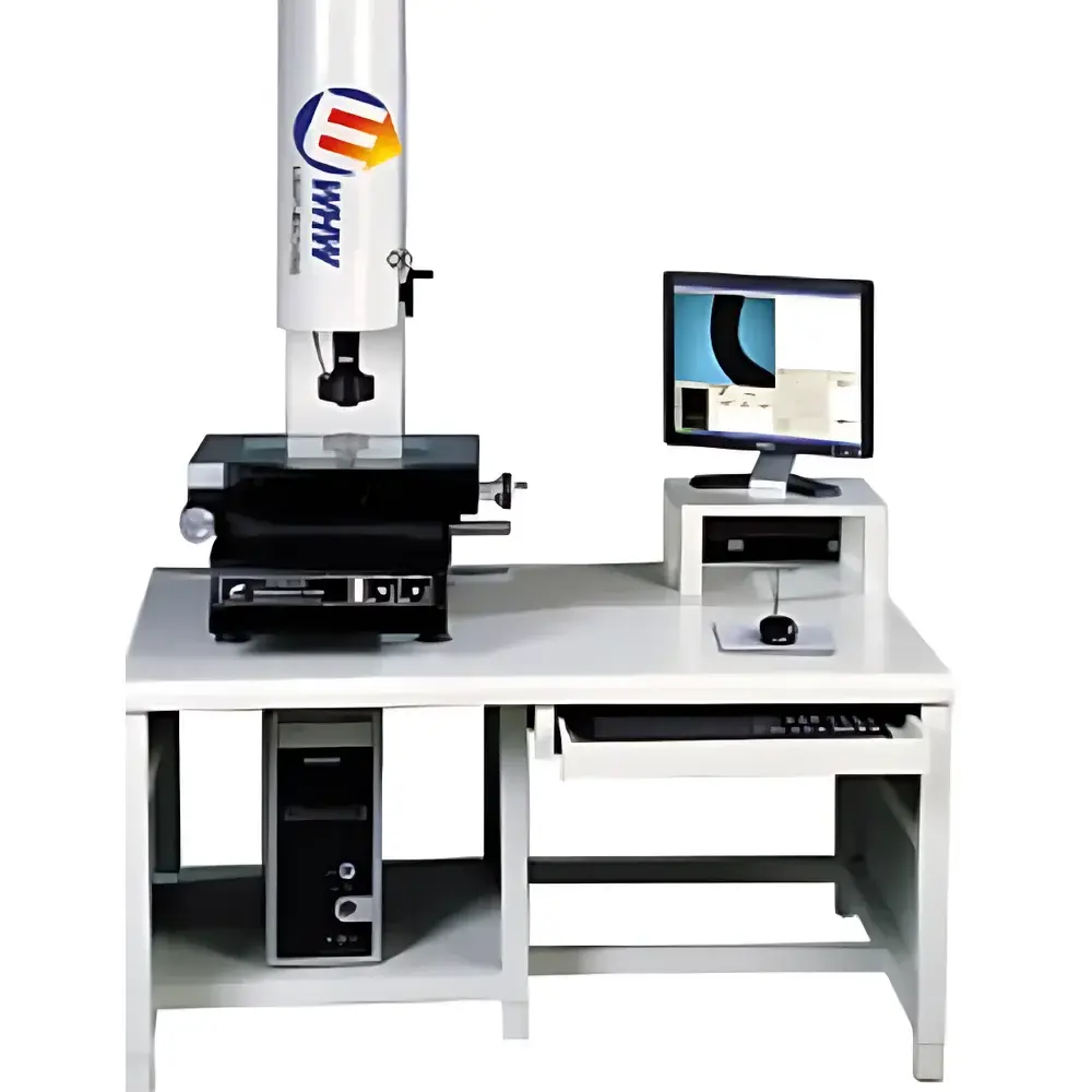
YANRUN YR-F1510 Practical Image Measuring System
| Brand | YANRUN |
|---|---|
| Origin | Shanghai, China |
| Manufacturer Type | Direct Manufacturer |
| Country of Origin | China |
| Model | YR-F1510 |
| Table Surface (Metal) | 354 × 228 mm |
| Table Surface (Glass) | 210 × 160 mm |
| Travel Range (X×Y) | 150 × 100 mm |
| Overall Dimensions (L×W×H) | 600 × 530 × 950 mm |
| Z-Axis Vertical Travel | 175 mm |
| Digital Readout Resolution (X/Y/Z) | 0.0005 mm |
| Positioning Accuracy (X/Y) | ≤(3 + L/200) µm |
| Imaging System | SONY Color CCD Camera |
| Objective Zoom Ratio | 0.7×–4.5× |
| Total Optical Magnification | 28×–180× |
| Illumination | Adjustable LED Surface & Transmission Light Sources |
| Power Supply | 220 V ±10%, 50 Hz |
| Operating Environment | 20 °C ±3 °C, 45–75% RH |
| Standard Software | Auto-edge detection, deburring, geometric feature measurement (point, line, circle, center-to-center distance, part alignment), and coordinate system registration |
Overview
The YANRUN YR-F1510 Practical Image Measuring System is a benchtop optical coordinate measuring instrument engineered for high-reproducibility 2D geometric metrology in quality control laboratories, precision machining workshops, and R&D environments. It operates on the principle of non-contact digital image acquisition and sub-pixel edge detection, leveraging a calibrated optical path, motorized zoom lens, and high-resolution SONY CCD sensor to translate physical object features into quantifiable Cartesian coordinates. Designed for routine inspection of machined parts, stamped components, PCBs, and small mechanical assemblies, the system delivers traceable dimensional verification without mechanical probing—minimizing part deformation risk and operator dependency. Its rigid granite base, thermally stable aluminum frame, and precision ground linear motion stages ensure mechanical stability under standard metrology lab conditions (20 °C ±3 °C, 45–75% RH). The system complies with foundational requirements of ISO 10360-7 (acceptance and reverification of vision measuring systems) and supports implementation within GLP/GMP-aligned workflows when paired with appropriate calibration protocols and audit-trail-enabled software configurations.
Key Features
- High-stability mechanical platform with 354 mm × 228 mm metal stage and 210 mm × 160 mm optical glass insert for simultaneous surface and transmitted-light measurement
- Precision X-Y translation stage with 150 mm × 100 mm travel range and 0.5 µm digital resolution across all axes (X/Y/Z)
- Optical imaging subsystem comprising a progressive-scan SONY color CCD camera and dual-mode telecentric zoom objective (0.7×–4.5×), enabling total magnifications from 28× to 180× with consistent depth-of-field
- Independent, dimmable LED ring light (surface illumination) and bottom-mounted LED backlight (transmitted illumination), each controllable via software for optimal contrast on reflective, translucent, or opaque samples
- Z-axis vertical adjustment with 175 mm lift capacity, facilitating focus optimization and multi-layer inspection without manual refocusing
- Integrated metrology-grade software supporting automatic edge detection, noise-resistant boundary extraction, and real-time error compensation per ISO 10360-7 Annex B guidelines
Sample Compatibility & Compliance
The YR-F1510 accommodates parts up to 150 mm in length and 100 mm in width, with maximum height clearance of 175 mm under the objective. Typical use cases include metallic stampings, plastic injection-molded housings, ceramic substrates, thin-film sensors, and precision gears. Sample mounting is facilitated by standard V-blocks, clamps, and kinematic fixtures compatible with ISO 10360-7 fixture classification. While the instrument itself does not carry CE or UKCA marking, its electrical design conforms to IEC 61000-6-3 (EMC emission limits) and IEC 61000-6-2 (immunity). When deployed with NIST-traceable step gauges and certified reference artifacts (e.g., PTB or NPL-certified grids), measurement results satisfy internal audit requirements for ISO 9001:2015 Clause 7.1.5 and support validation per ASTM E2500-13 (verification of analytical instruments).
Software & Data Management
The included measurement software provides a Windows-based GUI with programmable routines, batch report generation (PDF/Excel), and native support for GD&T symbols (ISO 1101). All measurement sessions log timestamped operator ID, environmental readings (if external sensors are connected), and raw image metadata—enabling full traceability. Audit trail functionality records parameter changes, calibration events, and result modifications, satisfying documentation prerequisites for FDA 21 CFR Part 11 if configured with electronic signature modules and role-based access controls. Export formats include CSV (for SPC analysis), DXF (for CAD comparison), and XML (for MES integration). Optional SDK allows custom API development for automated data ingestion into QMS platforms such as ETQ Reliance or MasterControl.
Applications
- Verification of critical dimensions on medical device components (e.g., catheter hubs, surgical instrument jaws) per ISO 13485 requirements
- First-article inspection of automotive connectors and micro-switches against APQP-defined control plans
- PCB solder paste deposit area and stencil aperture verification in electronics manufacturing
- Geometric tolerance assessment (position, concentricity, parallelism) on aerospace fasteners and turbine blade fixturing elements
- Educational use in metrology training labs for teaching fundamental concepts of optical magnification, pixel calibration, and uncertainty budgeting
FAQ
What calibration standards are recommended for daily verification?
A two-point ceramic step gauge (e.g., 1 mm and 10 mm certified steps) and a NIST-traceable grid target (100 µm pitch) are recommended for daily performance checks per ISO 10360-7 Section 6.2.
Is the system compatible with third-party metrology software?
Yes—the hardware exposes RS-232 and USB HID interfaces; OEM drivers and basic command protocols are available upon request for integration with PolyWorks, Metrolog X4, or custom LabVIEW applications.
Does the YR-F1510 support profile scanning or 3D surface reconstruction?
No—it is strictly a 2D image-based coordinate measuring system. For contour profiling or height mapping, consider YANRUN’s laser displacement sensor add-on modules or dedicated 3D CMM variants (e.g., YR-CMM series).
What is the recommended maintenance interval for optical alignment?
Annual verification of lens centering, CCD sensor orthogonality, and stage squareness is advised using manufacturer-provided alignment tools and documented procedures.
Can measurement reports be generated in multiple languages?
Yes—UI language and report templates support English, German, Japanese, and Simplified Chinese, configurable via software settings without reinstallation.