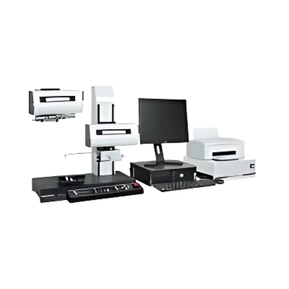
KOSAKA LAB SEF680 Surface Roughness and Profile Measuring System
| Origin | Guangdong, China |
|---|---|
| Manufacturer Type | Authorized Distributor |
| Origin Category | Domestic (China) |
| Model | KOSAKA LAB SEF680 |
| Pricing | Upon Request |
Overview
The KOSAKA LAB SEF680 Surface Roughness and Profile Measuring System is a dual-function precision metrology instrument engineered for traceable, high-resolution characterization of surface topography and geometric profile in industrial quality control and R&D laboratories. Based on contact stylus profilometry, the system employs a diamond-tipped probe traversing the sample surface under controlled force (typically 0.75 mN or 4 mN selectable), converting vertical displacement into analog voltage signals digitized at high sampling rates. Its core architecture integrates a high-stability granite base, air-bearing linear drive unit, and holographic grating encoder feedback for Z-axis positioning—enabling sub-nanometer resolution in vertical measurement and micron-level repeatability across extended travel ranges (up to 100 mm horizontal, 20 mm vertical). Designed for ISO/IEC 17025-compliant environments, the SEF680 serves as a primary reference tool for verifying surface finish specifications in aerospace components, medical device substrates, precision molds, and optical lens mounts.
Key Features
- Dual-mode operation: Simultaneous capability for surface roughness evaluation (per ISO 4287, ISO 13565, ISO 25178-2) and contour/profile geometry analysis (including radius, angle, step height, flatness, and form error).
- Comprehensive parameter library: Preconfigured support for over 50 standardized evaluation parameters aligned with ISO, DIN, ANSI/ASME B46.1, and JIS B 0601–2013 specifications—including Ra, Rz, Rq, Rsk, Rku, Rmr, Pc, and hybrid parameters such as Sk, Spk, and Svk.
- Holographic grating scale integration: Embedded 10 nm resolution Z-axis encoder ensures linearity stability better than ±0.1% over full stroke, minimizing Abbe error and thermal drift influence.
- Modular sensor head design: Tool-less, single-action mechanical coupling allows rapid interchange between roughness and profile measurement modules without cable re-routing or recalibration—reducing setup time by >60% compared to legacy systems.
- 45° tilt-adjustable drive unit: Motorized angular positioning enables optimal probe approach angles for complex geometries (e.g., internal bores, tapered surfaces, or undercut features), maintaining consistent tip-sample contact geometry.
- Ergonomic joystick controller: Intuitive three-axis manual navigation (X/Y/Z) with programmable speed ramping and tactile feedback—eliminating reliance on keyboard/mouse for coarse positioning and enhancing operator fatigue resistance during extended measurement sessions.
Sample Compatibility & Compliance
The SEF680 accommodates specimens up to 300 mm × 200 mm × 150 mm (L×W×H) with optional stage extensions. It supports metallic, ceramic, polymer, and coated substrates—including hardened steels (HRC 65+), sapphire wafers, and PVD-coated turbine blades. All measurement algorithms adhere to ISO 25178-601 (areal surface texture) and ISO 11562 (filtering methodology), ensuring data interoperability with coordinate measuring machines (CMMs) and optical profilers. The system’s calibration certificate includes traceability to NIM (National Institute of Metrology, China) and optionally to PTB (Physikalisch-Technische Bundesanstalt) via accredited third-party verification. Full audit trail functionality satisfies GLP and GMP documentation requirements per FDA 21 CFR Part 11 when paired with KOSAKA’s optional SecureLog software module.
Software & Data Management
Equipped with KOSAKA’s SURFPAK-V3 analysis suite (Windows 10/11 compatible), the SEF680 delivers automated report generation in PDF, CSV, and XML formats—with embedded metadata (operator ID, timestamp, environmental conditions, calibration status). Filtering options include Gaussian, Spline, and Robust Gaussian per ISO 16610-21; spectral analysis supports power spectral density (PSD) and autocorrelation function (ACF) outputs. Raw data export preserves 16-bit depth and native XYZ point cloud structure for downstream processing in MATLAB, Python (NumPy/SciPy), or metrology-specific platforms like PolyWorks or MountainsMap. Role-based user permissions, electronic signatures, and revision-controlled template libraries ensure compliance with ISO 9001:2015 Clause 7.1.5.2 (Measurement Traceability).
Applications
- Automotive: Cylinder bore honing texture analysis, gear flank roughness validation, and brake disc waviness assessment.
- Medical Devices: Surface finish verification of orthopedic implants (ASTM F2715), stent strut edge definition, and dental CAD/CAM abutment geometry.
- Semiconductor Packaging: Leadframe coplanarity, mold cavity replication fidelity, and wafer-level bump height uniformity.
- Optics Manufacturing: Lens mount interface flatness, aspheric mold master verification, and anti-reflective coating substrate roughness screening.
- Aerospace: Turbine blade trailing edge radius, thermal barrier coating spallation zone profiling, and fastener thread root roughness mapping.
FAQ
What standards does the SEF680 comply with for surface roughness measurement?
The system implements algorithms and filtering methods fully compliant with ISO 4287:1997, ISO 13565-1/2/3, ISO 25178-2, JIS B 0601:2013, and ANSI/ASME B46.1–2019.
Can the SEF680 measure both roughness and contour on the same sample without repositioning?
Yes—its modular probe carriage and synchronized X-Z motion control allow sequential acquisition of roughness traces and full-profile scans from identical datum references, eliminating relocation-induced alignment errors.
Is calibration documentation provided with the instrument?
Each unit ships with a factory calibration report traceable to NIM, including Z-axis linearity, stylus tip radius verification (2 µm nominal), and filter cutoff accuracy validation.
Does the system support automated batch measurement for production floor deployment?
Via SURFPAK-V3’s MacroScript engine and optional PLC interface (RS-232/Modbus TCP), users can define repeatable measurement routines triggered by external sensors or MES commands.
What is the maximum allowable sample weight and height clearance?
Standard configuration supports samples up to 25 kg and 150 mm height; custom high-clearance stages (up to 300 mm) and heavy-duty bases (50 kg capacity) are available upon request.
Related Products