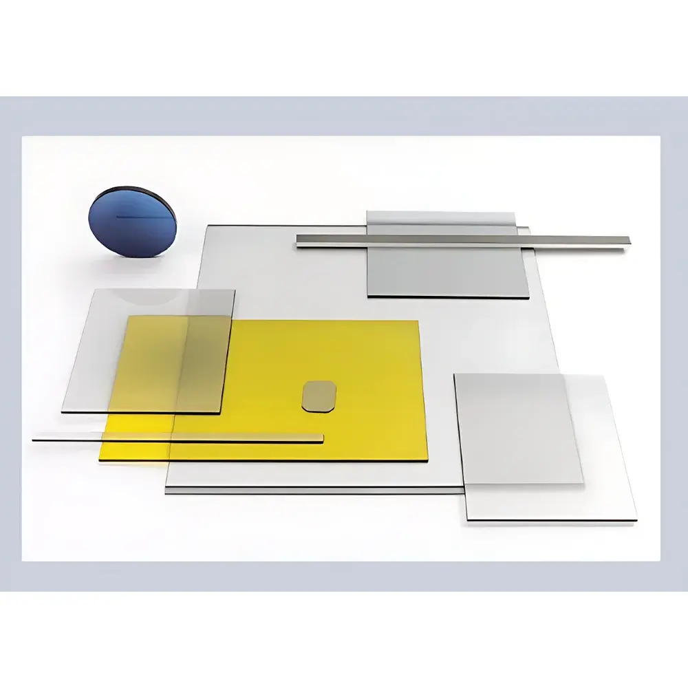
Fiber Optic Taper Panel (Customizable Size)
| Brand | Auniontech |
|---|---|
| Origin | Imported |
| Manufacturer Type | Authorized Distributor |
| Model | Fiber Optic Panel |
| Pricing | Upon Request |
Overview
The Auniontech Fiber Optic Taper Panel is a precision-engineered optical coupling component designed for high-performance digital radiography (DR) and X-ray imaging systems. It functions as a direct, hermetic interface between scintillator materials (e.g., CsI:Tl, Gd2O2S:Tb) and image sensors (CCD or CMOS), enabling efficient light transmission while minimizing photon loss, spatial distortion, and sensor degradation. Based on fused silica fiber bundle architecture with sub-micron core pitch and controlled taper ratio, the panel operates on the principle of total internal reflection (TIR) to preserve spatial fidelity across the entire active area. Its primary role is to optically demagnify or collimate scintillation light emitted from the phosphor layer—thereby increasing effective pixel fill factor at the sensor plane—while simultaneously attenuating incident X-ray flux that would otherwise damage or induce noise in semiconductor photodetectors.
Key Features
- Optical coupling efficiency exceeding 65% (measured at 550 nm peak emission wavelength of CsI:Tl), optimized via anti-reflective (AR) coating on both input and output faces
- Active area customizable up to 490 mm × 320 mm, with dimensional tolerance ≤ ±0.15 mm and surface flatness < λ/4 @ 633 nm
- Fiber core diameter ranging from 6 µm to 12 µm, enabling resolution preservation down to 83 lp/mm (line pairs per millimeter) under ideal illumination conditions
- Thermal expansion coefficient matched to common scintillator substrates (e.g., glass or aluminum), reducing interfacial stress during thermal cycling
- Hermetically sealed edge finish to prevent moisture ingress and fiber bundle delamination over extended operational lifetimes (>10 years under controlled lab environments)
- Compatible with vacuum-bonding and epoxy-based optical adhesion processes used in industrial DR detector assembly lines
Sample Compatibility & Compliance
The panel supports integration with industry-standard scintillators including thallium-doped cesium iodide (CsI:Tl), terbium-doped gadolinium oxysulfide (Gd2O2S:Tb), and newer ceramic phosphors such as Gd3Al5O12:Ce (GAGOC). Its mechanical and optical specifications conform to requirements outlined in IEC 62220-1-1:2015 (characteristics of medical X-ray imaging detectors) and ASTM E2737-21 (standard guide for digital radiographic system performance evaluation). While not a finished medical device itself, the panel is manufactured under ISO 9001-certified quality management systems and complies with RoHS Directive 2011/65/EU and REACH Regulation (EC) No. 1907/2006 for restricted substances.
Software & Data Management
As a passive optical component, the Auniontech Fiber Optic Panel does not incorporate embedded firmware or require driver installation. However, its geometric and optical characteristics are fully parameterized in standard detector calibration workflows used by OEMs and system integrators. It supports seamless integration into DICOM-compliant imaging pipelines when paired with compliant X-ray detectors. For QA/QC traceability, each panel is supplied with a Certificate of Conformance (CoC) listing batch-specific measurements—including center thickness uniformity, surface roughness (Ra < 5 nm), and spectral transmittance curves (350–700 nm). Audit-ready documentation aligns with GLP and GMP-aligned manufacturing practices, including full lot traceability and raw material certifications from fused silica suppliers.
Applications
- Digital radiography (DR) detectors for veterinary and human diagnostic imaging systems
- Non-destructive testing (NDT) equipment used in aerospace, automotive, and nuclear inspection applications
- High-resolution micro-CT detector modules requiring low geometric unsharpness and minimal light spread
- Scientific imaging setups involving synchrotron radiation or neutron radiography where sensor protection and signal fidelity are critical
- Custom hybrid detectors combining scintillator layers with scientific-grade sCMOS or EMCCD sensors
FAQ
What is the maximum operating temperature range for long-term use?
The panel is rated for continuous operation between −20 °C and +60 °C; short-term excursions up to +85 °C are permissible for ≤2 hours without permanent optical degradation.
Can the panel be cleaned with isopropyl alcohol or acetone?
Yes—both surfaces may be gently wiped using lint-free wipes saturated with spectroscopic-grade isopropyl alcohol (IPA); acetone is not recommended due to potential binder interaction with AR coatings.
Is vacuum bonding supported?
Yes—the input face is polished to λ/10 surface quality and compatible with vacuum-compatible optical adhesives (e.g., Norland NOA61, Epotek OG116-31) for permanent bonding to scintillator substrates.
Do you provide optical simulation files (Zemax or CODE V format)?
Upon NDA execution, we supply non-proprietary ray-trace models describing nominal taper geometry, numerical aperture (NA = 1.0 ± 0.02), and bulk absorption coefficients for modeling light propagation efficiency.
Are panels available with AR coatings optimized for specific scintillator emission bands?
Yes—custom multi-layer AR coatings can be applied for peak transmission at 420 nm (Gd2O2S:Tb), 550 nm (CsI:Tl), or 530 nm (GAGOC), with average reflectivity <0.5% across ±20 nm bandwidth.