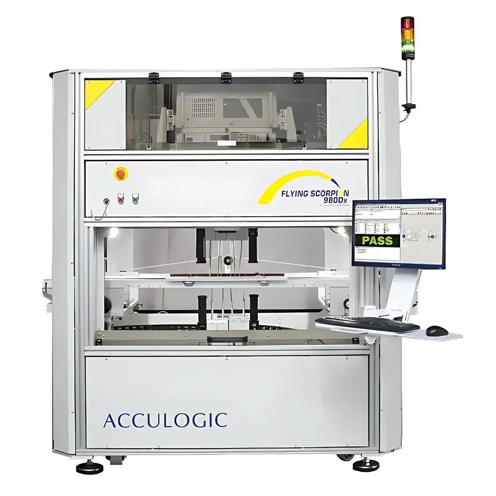
Acculogic FLS980 Series III Flying Probe Test System
| Brand | Acculogic |
|---|---|
| Origin | Canada |
| Model | FLS980 Series III |
| Positioning Repeatability | ±10 µm |
| Minimum Step Resolution | 1 µm |
| Maximum PCB Size | 813 × 965 mm (32" × 38") |
| Programmable Probe Angle | ±6° |
| Max. Probe Count (Top + Bottom) | 22 |
| Measurement Speed | Up to 1000 measurements/sec |
| Electrical Test Capabilities | Analog, Digital, Mixed-Signal, Boundary Scan (JTAG), Powered Functional Test (up to GHz range) |
| Warpage Compensation | LaserScan-enabled Z-axis mapping |
| Vision System | High-resolution fiducial camera with advanced image processing |
| Compliance Support | ASTM F2413-18 (for test system validation), ISO/IEC 17025 traceability framework, GLP/GMP-aligned audit trail in Integrator™ software |
Overview
The Acculogic FLS980 Series III Flying Probe Test System is a high-precision, dual-sided automated test platform engineered for functional and parametric verification of printed circuit board assemblies (PCBAs) in low-to-medium volume, high-mix electronics manufacturing environments. Unlike traditional bed-of-nails in-circuit testers (ICT), the FLS980 employs a non-contact, programmable flying probe architecture based on closed-loop linear motor shuttles and kinematically decoupled probe modules. Its core measurement principle integrates real-time vision-guided motion control, laser-based board warpage mapping, and multi-channel analog/digital stimulus-response acquisition — enabling reliable electrical access to ultra-fine-pitch components (e.g., 01005, 0201, and chip-scale packages) where physical test fixtures are impractical or cost-prohibitive. Designed for evolving SMT assembly challenges—including reduced test pad availability, increased component density, and board-level thermal deformation—the system delivers repeatable electrical contact under dynamically compensated XYZ coordinates, supporting both unpowered continuity/isolation tests and powered functional validation across RF-relevant signal bands.
Key Features
- Closed-loop shuttle architecture with 1 µm minimum step resolution and ±10 µm positioning repeatability across X, Y, and Z axes
- Dual-sided probing capability supporting up to 22 independently controlled flying probes (top and bottom combined)
- Programmable probe angle module (APM 800) with ±6° continuous tilt adjustment for optimized contact geometry on warped or uneven boards
- LaserScan Z-mapping subsystem for real-time board warpage compensation—critical for maintaining probe tip alignment on SMT-assembled PCBs exhibiting >0.3 mm deflection
- High-resolution fiducial camera with sub-pixel centroid detection and adaptive lighting, integrated with advanced image processing for robust fiducial recognition under variable solder mask conditions
- Integrator™ control software featuring deterministic motion scheduling, synchronized stimulus timing, and embedded measurement algorithms compliant with IEEE 1149.1 (JTAG) and IEEE 1149.6 (AC-JTAG) standards
- 4-wire Kelvin measurement capability across all 22 probes, supporting precision resistance, capacitance, inductance, diode, transistor, and IC pin-level parametric characterization
- Powered functional test mode with programmable voltage/current sourcing (±20 V, ±1 A), enabling live validation of regulators, op-amps, DC-DC converters, and mixed-signal ICs up to GHz-range signal integrity thresholds
Sample Compatibility & Compliance
The FLS980 Series III accommodates PCBAs ranging from prototype hand-soldered assemblies to production-grade SMT boards up to 813 × 965 mm (32″ × 38″), with maximum component height of 85 mm and probe-accessible features down to 100 µm pitch. It supports rigid, flex-rigid, and multilayer boards with standard FR-4, polyimide, and high-frequency laminates (e.g., Rogers RO4000®). The system meets mechanical and electrical safety requirements per CSA C22.2 No. 61010-1 and UL 61010-1. Measurement traceability aligns with ISO/IEC 17025:2017 clauses for calibration of test instrumentation, while software audit trails—including user actions, parameter changes, and result exports—support GLP and GMP documentation requirements under FDA 21 CFR Part 11 when configured with electronic signature modules. Boundary scan test sequences comply with IEEE Std 1149.1-2013 and support BSDL file import for automatic test vector generation.
Software & Data Management
Integrator™ is the native control and analysis suite for the FLS980 platform, providing unified management of motion planning, test program development, real-time diagnostics, and data archival. Test programs are authored using hierarchical test plan structures with modular test steps (continuity, isolation, analog parametric, JTAG, NetScan™), each assignable to specific probe groups and coordinate frames. All measurement data—including raw ADC samples, calculated parameters, pass/fail flags, and timestamped images—is stored in vendor-neutral SQLite databases with optional export to CSV, XML, or industry-standard IPC-D-356 formats. Audit logs record operator login/logout events, test execution history, calibration status, and firmware revision metadata. Optional integration with MES platforms (e.g., Siemens Opcenter, Camstar) is supported via RESTful API and OPC UA interfaces, enabling automated job dispatch, SPC data streaming, and nonconformance reporting workflows.
Applications
- Low-volume/high-mix NPI validation for automotive ADAS modules, medical PCBAs, and aerospace avionics where fixtureless test flexibility is mandatory
- Failure analysis labs performing root-cause investigation of solder joint voiding, tombstoning, or interconnect opens via targeted parametric probing
- Contract manufacturers requiring rapid test program turnaround for customer-supplied designs without dedicated ICT fixture investment
- Reverse engineering support through automated net identification (NetScan™), component footprint mapping, and boundary scan chain reconstruction
- Thermal stress validation—combining powered functional test with infrared thermography synchronization to detect current-path anomalies under load
- Post-reflow inspection correlation—using laser warpage maps and vision-based fiducial offsets to correlate electrical test failures with physical board deformation
FAQ
What is the smallest component pitch the FLS980 Series III can reliably test?
The system achieves repeatable electrical contact on targets as small as 100 µm in diameter using 50–500 µm tip-radius probes; validated for 01005 passive components and fine-pitch QFN packages with ≥0.4 mm lead pitch.
Does the FLS980 support JTAG boundary scan testing?
Yes—it includes full IEEE 1149.1-compliant boundary scan controller hardware and software, with BSDL parser, chain integrity verification, and EXTEST/INTEST vector generation capabilities.
How does the system compensate for PCB warpage during probing?
LaserScan acquires >10,000 Z-height points across the board surface prior to test execution; this point cloud is interpolated into a continuous elevation model used to dynamically adjust probe Z-position and tip angle in real time.
Can the FLS980 perform powered functional testing at RF frequencies?
While not a vector network analyzer, it supports functional validation of RF subsystems (e.g., LNA bias networks, PA enable logic, PLL lock detection) up to 3 GHz using high-bandwidth analog front-ends and synchronized digital I/O.
Is third-party calibration documentation available for metrological traceability?
Acculogic provides NIST-traceable calibration certificates for motion encoders, laser displacement sensors, and analog measurement channels, issued annually or per ISO/IEC 17025-accredited laboratory protocols.