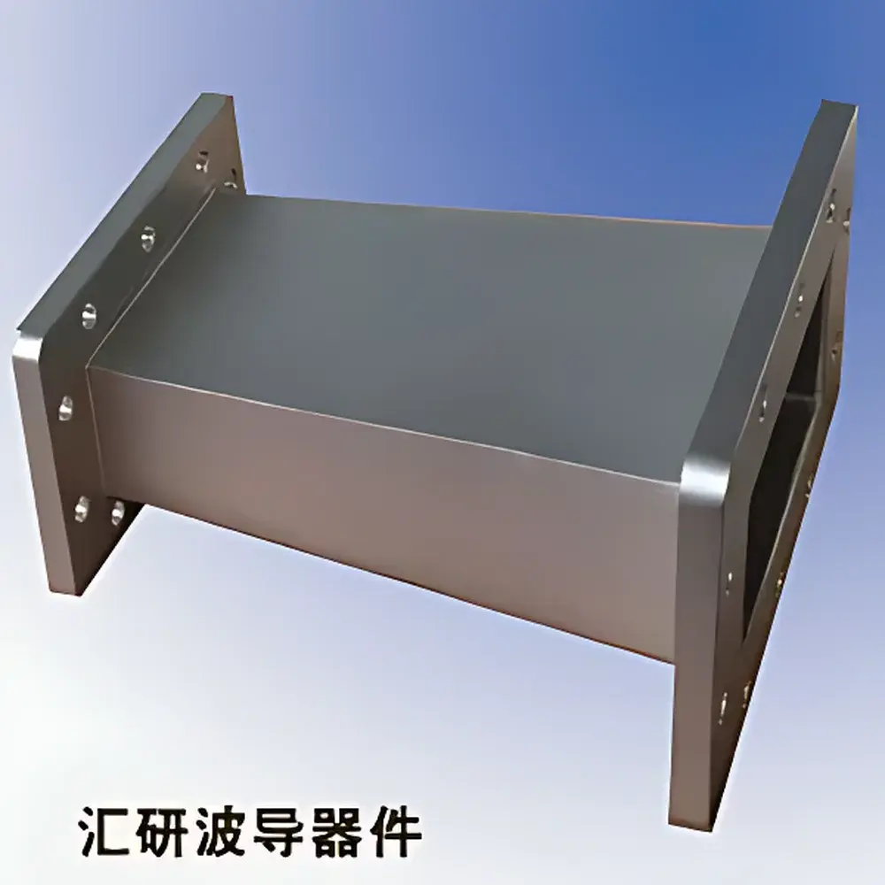
BJ26 to BJ32 Rectangular Waveguide Transition
| Brand | Huiyan |
|---|---|
| Origin | Jiangsu, China |
| Manufacturer Type | Authorized Distributor |
| Origin Category | Domestic (PRC) |
| Model | BJ26-BJ32 |
| Pricing | Upon Request |
Overview
The BJ26 to BJ32 Rectangular Waveguide Transition is a precision-machined passive microwave component engineered to provide low-loss, broadband impedance matching between WR-284 (BJ-26) and WR-229 (BJ-32) standard rectangular waveguides. Designed in strict accordance with IEEE Std 178 and IEC 60153-2 specifications for waveguide dimensional tolerances and surface finish, this transition enables seamless integration in high-power and high-frequency test benches, antenna feed networks, and radar subsystems operating within the S-band (2.6–3.95 GHz) and lower C-band (3.95–5.85 GHz). The device operates on the fundamental TE10 mode propagation principle, with optimized taper geometry minimizing higher-order mode excitation and ensuring return loss better than −30 dB across its operational bandwidth. Its all-metal construction—typically using oxygen-free copper or aluminum with silver or gold plating—guarantees thermal stability, corrosion resistance, and long-term RF performance consistency under continuous-wave (CW) or pulsed power conditions up to 10 kW peak.
Key Features
- Precision CNC-machined brass or aluminum body with electroplated silver/gold internal surfaces for minimal insertion loss (typical < 0.05 dB) and high conductivity
- Monolithic stepped-taper design eliminating flange misalignment risks and maintaining E-plane/H-plane symmetry
- Standard UG-39/U and UG-40/U flanges (per MIL-DTL-3922/67) with knife-edge contact interface and 16–20 µin Ra surface roughness
- Hermetically sealed option available for pressurized or vacuum-compatible systems (e.g., satellite payload testing)
- Thermal expansion coefficient matched to adjacent waveguide sections to prevent mechanical stress-induced VSWR degradation
- Compliant with MIL-STD-202G for vibration, shock, and thermal cycling qualification
Sample Compatibility & Compliance
This transition is fully compatible with legacy and modern waveguide systems adhering to the IEEE Standard Radar Band Designations (BJ-series nomenclature), including but not limited to systems from Keysight, Rohde & Schwarz, Anritsu, and TMD. It supports both air-filled and SF6-pressurized configurations. All units undergo 100% vector network analyzer (VNA) verification at 2.5–6.0 GHz using calibrated S-parameter measurement (S11/S21) per IEC 61000-4-3 radiated immunity pre-scan protocols. Documentation includes traceable calibration certificates compliant with ISO/IEC 17025:2017, and optional RoHS 3 and REACH declarations are provided upon order.
Software & Data Management
While inherently hardware-based and requiring no embedded firmware, the transition integrates transparently into automated test systems via SCPI-command-driven VNAs (e.g., Keysight PNA-X series) or MATLAB/Simulink-based RF modeling workflows. S-parameter touchstone (.s2p) files are supplied for EM simulation validation in CST Studio Suite, HFSS, or FEKO. For quality assurance traceability, each unit is assigned a unique serial number linked to manufacturing lot data—including raw material mill certs, dimensional inspection reports (CMM), and RF test logs—stored in a secure, audit-ready database meeting GLP and ISO 9001:2015 record retention requirements.
Applications
- S-band radar transceiver front-end interfacing between high-power klystron amplifiers (WR-284 output) and antenna array feed networks (WR-229 input)
- Calibration path extension in metrology-grade microwave anechoic chambers and far-field range facilities
- EMC immunity test setup adaptation for automotive radar modules requiring band-specific waveguide routing
- Research-grade plasma diagnostics where stable, mode-pure coupling into cavity resonators is critical
- Defense electronics upgrades involving legacy system modernization without full waveguide re-engineering
FAQ
What is the maximum average power rating for continuous operation?
Rated for 2.5 kW average power at 25°C ambient with forced-air cooling; derating applies above 40°C per MIL-STD-704F Annex B.
Is custom flange configuration supported (e.g., CPR-137 or blind-mate)?
Yes—custom flange types, torque specifications, and gasket groove profiles can be implemented per customer drawing, subject to NDA and minimum order quantity.
Does the transition support dual-polarization or orthogonal mode transduction?
No—it is strictly single-mode (TE10) and polarization-preserving; cross-polarization coupling is suppressed to < −45 dB across band.
Can this component be used in space-qualified assemblies?
Yes—space-grade variants are available with outgassing-tested materials (per ECSS-Q-ST-70-02C), radiation-hardened plating, and extended thermal vacuum cycling certification.
How is mechanical alignment verified during installation?
Each unit includes alignment pin holes per MIL-DTL-3922/67, and a dedicated go/no-go gauge set is supplied for field verification of flange coplanarity and centering tolerance (±0.025 mm).


