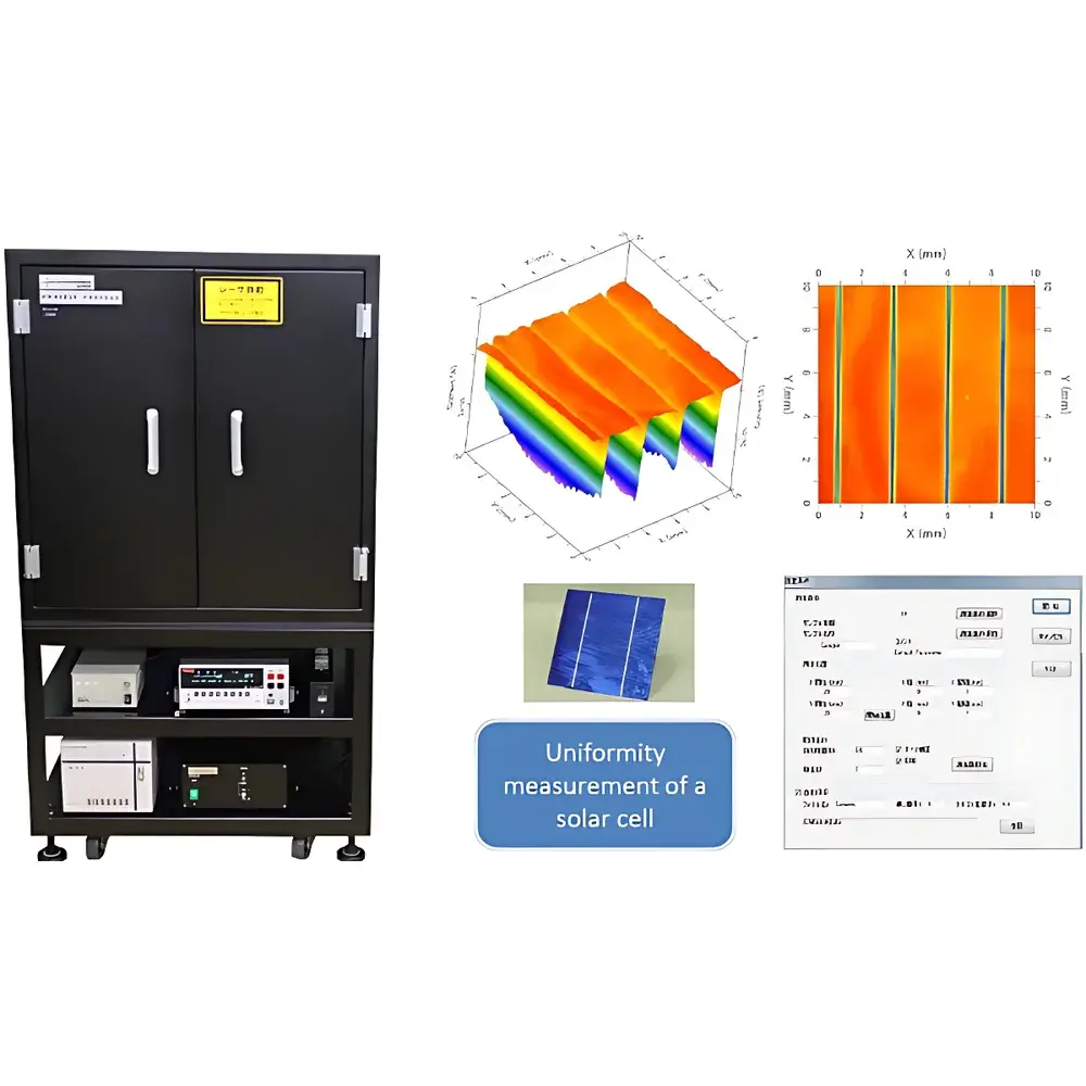
LBC-1 Laser-Induced Current Mapping System
| Origin | Japan |
|---|---|
| Manufacturer Type | Authorized Distributor |
| Origin Category | Imported |
| Model | LBC-1 |
| Price Range | USD 110,000 – 138,000 |
| Laser Wavelength | 532 nm (Green) |
| Laser Power Output | 10 mW |
| Beam Stability | ±2% |
| Spot Size | Ø100 µm |
| Maximum Scan Area | 50 mm × 50 mm (X-Y Stage Travel: ±30 mm) |
| Photocurrent Measurement Range | 10 pA – 1 A (Keithley Model 2401) |
| Irradiation Configuration | Top-side or Bottom-side (Optional) |
Overview
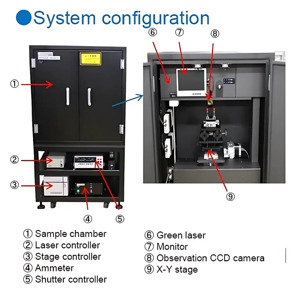
The LBC-1 Laser-Induced Current Mapping System is a precision semiconductor characterization instrument engineered for spatially resolved photocurrent analysis of photovoltaic devices. It operates on the principle of laser-induced current transient (LICT) mapping—where a focused, wavelength-specific laser beam (532 nm green light) locally excites charge carriers in a semiconductor junction, generating a measurable photocurrent proportional to local quantum efficiency, defect density, and carrier collection uniformity. Unlike bulk electrical testing, this technique provides micron-scale lateral resolution (Ø100 µm spot size) across active device areas up to 50 mm × 50 mm, enabling quantitative evaluation of spatial heterogeneity in perovskite, silicon, CIGS, and organic photovoltaic cells. The system integrates a high-stability diode-pumped solid-state (DPSS) laser (±2% power stability), a motorized high-precision X-Y translation stage (±0.5 µm repeatability), and a low-noise current measurement subsystem based on the Keithley Model 2401 SourceMeter—capable of resolving currents from 10 pA to 1 A with 6½-digit resolution and sub-femtoampere noise floor in guarded mode.
Key Features
- High-resolution photocurrent mapping with Ø100 µm laser spot size and <1 µm positional accuracy via closed-loop stepper control
- Configurable irradiation geometry: standard top-side illumination; optional bottom-side configuration for back-contact or transparent-substrate devices
- Real-time sample observation monitor with integrated coaxial optical path—enabling precise alignment of laser focus relative to device features (e.g., grid lines, edge defects, interconnects)
- Stable 532 nm DPSS laser source (10 mW output) optimized for Si and perovskite bandgap excitation, delivering consistent photon flux for reproducible S/N ratios (>60 dB typical)
- Modular architecture compliant with ISO/IEC 17025 laboratory infrastructure requirements—designed for integration into GLP/GMP-qualified QA workflows
Sample Compatibility & Compliance
The LBC-1 accommodates rigid and flexible substrates including glass, silicon wafers, PET, and stainless-steel foils, with thicknesses ranging from 100 µm to 2 mm. Samples are mounted on vacuum chucks or mechanical clamps compatible with standard 4-inch and 6-inch wafer carriers. All optical and electrical interfaces adhere to IEC 61215-2 (photovoltaic module qualification) and ASTM F2890-22 (standard practice for evaluating thin-film solar cell uniformity). Data acquisition protocols support traceable calibration against NIST-traceable reference cells (e.g., KG5-filtered Si reference diodes), fulfilling metrological requirements for ISO 17025-accredited laboratories. The system’s electromagnetic shielding and grounded chassis meet EN 61326-1 for EMC compliance in industrial lab environments.
Software & Data Management
Control and analysis are performed via LBC-MAP v3.2 software—a Windows-based application supporting automated raster scanning, user-defined ROI selection, and real-time current vs. position visualization. Raw data are stored in HDF5 format with embedded metadata (timestamp, laser power, stage coordinates, ambient temperature/humidity). Software includes built-in statistical tools for calculating uniformity metrics: relative standard deviation (RSD), max/min ratio, and spatial autocorrelation length. Audit trails comply with FDA 21 CFR Part 11 requirements, featuring electronic signatures, role-based access control, and immutable log files. Export options include CSV, MATLAB .mat, and TIFF (for false-color maps), facilitating downstream analysis in Python (NumPy/SciPy), OriginLab, or MATLAB.
Applications
- Quantitative assessment of current uniformity in perovskite solar cells—identifying pinhole-related shunt paths, phase segregation domains, and interfacial recombination gradients
- Process validation of screen-printed Ag paste sintering on crystalline Si cells—correlating local series resistance variations with finger line continuity
- Failure analysis of tandem cell stacks—localizing current mismatch between subcells via spectral-selective laser scanning (with optional wavelength tuning module)
- Quality control of R2R-manufactured OPV modules—mapping photocurrent decay along web direction to detect coating non-uniformity or electrode delamination
- Research-grade characterization of emerging photoelectrochemical (PEC) electrodes—evaluating catalytic site distribution under simulated AM1.5G illumination
FAQ
What is the minimum resolvable photocurrent with the LBC-1 system?
The system achieves 10 pA resolution using the Keithley 2401 in low-current mode with external guarding and averaging over 10 PLC cycles—validated per IEC 62670 Annex B.
Can the LBC-1 be used for time-resolved photocurrent measurements?
No—the standard configuration performs steady-state mapping only. Time-resolved capability (ns–ms range) requires optional pulsed laser module (LBC-PULSE-532) and digitizer upgrade (Keysight M3202A PXIe).
Is the laser safety class certified?
Yes—the integrated 532 nm laser complies with IEC 60825-1:2014 Class 3B, with interlocked enclosure, emission indicator LED, and key-controlled enable switch.
Does the system support automated pass/fail binning based on uniformity thresholds?
Yes—LBC-MAP v3.2 allows definition of spatial uniformity criteria (e.g., RSD < 5% over central 80% area), triggering automatic classification and CSV report generation.
How is thermal drift compensated during extended scans?
Stage thermal expansion is mitigated by an internal Pt100 sensor feeding real-time correction coefficients to the motion controller; ambient temperature is logged continuously and flagged if exceeding 23 ± 2 °C.