Optiphase MFI1050 / MFI1350 / MFI1550 Fiber Michelson Interferometer
| Brand | Optiphase |
|---|---|
| Origin | USA |
| Model | MFI-10-50, MFI-13-50, MFI-15-50 |
| Operating Wavelength | 1064 nm, 1310 nm, 1550 nm |
| Insertion Loss | <1.5 dB |
| Optical Path Difference (OPD) Mismatch | 0 m (nominal), ±10 cm tolerance |
| Modulation Constant | 2.5 rad/V (1064 nm), 2.0 rad/V (1310 nm), 1.6 rad/V (1550 nm) |
| PZT Drive Interface | BNC |
| Max Optical Power Handling | 250 mW |
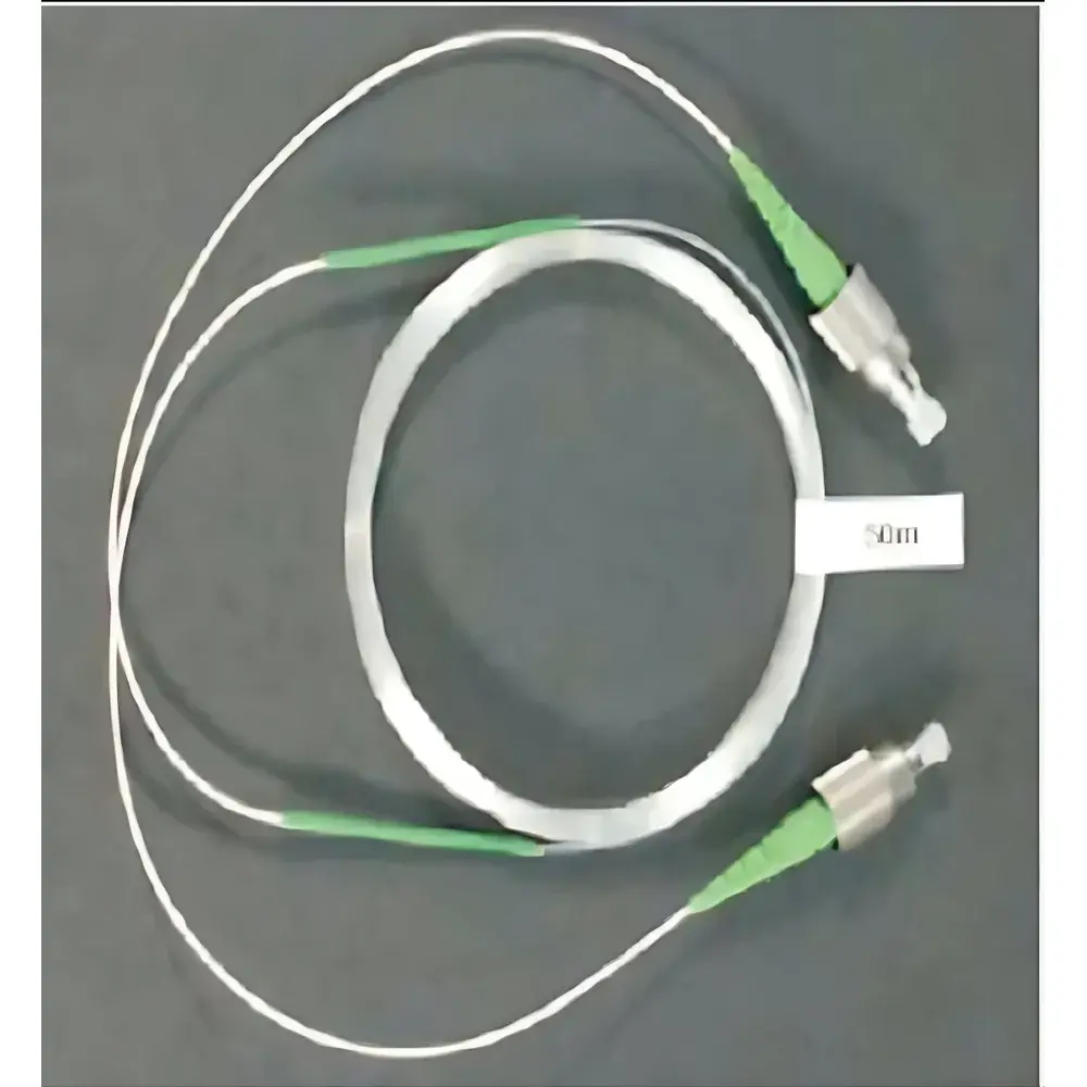
| Delay Fiber Length (standard) | 50 m (customizable from 0.5 m to 1000 m) |
| Fiber Type | HI-1060 (1064 nm), SMF-28e (1310/1550 nm) |
| Connector | FC/APC |
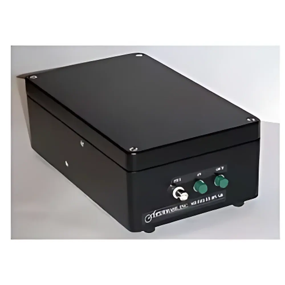
| Package Dimensions | 260 × 160 × 90 mm |
| Weight | ~2.7 kg |
Overview
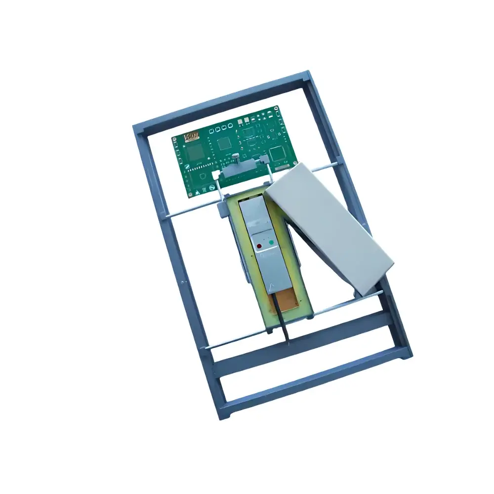
The Optiphase MFI1050, MFI1350, and MFI1550 are all-fiber Michelson interferometers engineered for high-stability, low-noise optical phase measurement and dynamic interferometric sensing applications. Based on the classical Michelson configuration implemented entirely in single-mode fiber, these instruments operate on the principle of coherent interference between two spatially separated optical paths—each formed by a fused fiber coupler, matched arm lengths, and reflective terminations. The core architecture eliminates free-space alignment, minimizing sensitivity to vibration, thermal drift, and environmental perturbations. A key design feature is the “zero-meter” nominal optical path difference (OPD), enabling precise user-defined delay tuning via integrated piezoelectric fiber stretchers (PZ1 series). This zero-mismatch baseline ensures maximum fringe visibility and phase linearity at quadrature bias—critical for accurate laser phase noise characterization and demodulation-based sensor emulation. Each model is optimized for its designated wavelength band (1064 nm, 1310 nm, or 1550 nm), with corresponding fiber selection (HI-1060 or SMF-28e), polarization-maintaining compatibility, and APC-terminated FC connectors to suppress back reflections.
Key Features
- All-fiber monolithic construction ensures long-term stability, mechanical robustness, and immunity to air-path disturbances
- Zero-nominal OPD design with ±10 cm arm-length matching tolerance supports high-visibility interference and repeatable quadrature biasing
- Integrated PZT-driven fiber stretcher (PZ1-compatible) with front-panel BNC modulation input for real-time phase actuation (2.5–1.6 rad/V, wavelength-dependent)
- Low insertion loss (<1.5 dB typical) preserves signal-to-noise ratio in sensitive detection chains
- Standard 50 m delay coil (customizable from 0.5 m to 1000 m) enables flexible simulation of distributed fiber sensor lengths
- Bare-fiber (unhoused) variant available for OEM integration into vacuum chambers, cryogenic systems, or custom optomechanical mounts
- FC/APC connectors minimize return loss (<–60 dB) and support polarization-controlled operation when paired with PM fiber components
Sample Compatibility & Compliance
The MFI series is compatible with continuous-wave (CW) semiconductor lasers, fiber-pigtailed DFB/DBR sources, and amplified spontaneous emission (ASE) sources operating within specified wavelength bands. It supports input power levels up to 250 mW without nonlinear effects or thermal damage to the fused couplers or delay coil. The device complies with IEC 61300-2-4 (fiber optic connector durability) and Telcordia GR-1209-CORE (reliability of passive fiber components). While not certified as medical or industrial safety equipment, its design adheres to laser safety principles per ANSI Z136.1 when used with appropriate optical attenuation and beam containment. For GLP/GMP-regulated environments, traceable calibration records and configurable audit logs (when interfaced with compliant data acquisition systems such as OPD-4000) support 21 CFR Part 11-aligned workflows.
Software & Data Management
The MFI interferometers are hardware-transparent and designed for seamless integration with third-party phase demodulation platforms—including the Optiphase OPD-4000 digital phase analyzer. They accept analog control voltages (via BNC) for PZT biasing and support both analog voltage output and digital (USB/Ethernet) phase data streaming. When coupled with validated software environments (e.g., MATLAB Instrument Control Toolbox, LabVIEW FPGA modules, or Python-based PyVISA drivers), users can implement closed-loop quadrature tracking, real-time FFT-based noise spectral density estimation (e.g., Hz²/Hz or rad²/Hz), and time-domain phase unwrapping. All firmware and driver packages undergo version-controlled release cycles with SHA-256 integrity verification; metadata embedding (timestamp, wavelength, calibration ID) is supported in exported .csv and HDF5 formats for FAIR (Findable, Accessible, Interoperable, Reusable) data management.
Applications
- Laser phase and frequency noise metrology: Used with balanced photodetectors and spectrum analyzers to quantify linewidth, flicker noise, and white frequency noise in DFB, DBR, and external cavity diode lasers
- Interferometric fiber sensor emulation: Simulates Mach-Zehnder or Sagnac configurations by adjusting delay length to replicate strain, temperature, or acoustic response profiles of embedded FBG or distributed acoustic sensing (DAS) systems
- Coherent optical receiver testing: Validates IQ modulator linearity, carrier suppression, and local oscillator phase-lock stability in advanced modulation formats (QPSK, 16-QAM)
- Fundamental optics research: Supports studies in quantum optics (e.g., Hong–Ou–Mandel interference), optical coherence tomography (OCT) reference arm development, and gravitational wave detector prototype validation
- Industrial process monitoring: Integrated into feedback loops for ultra-precise laser stabilization in semiconductor lithography tools and atomic clock subsystems
FAQ
What is the significance of the “zero-meter” optical path difference specification?
It denotes that the physical lengths of the two interferometer arms are matched to within ±10 cm at the factory—enabling immediate operation at high-contrast interference without manual balancing. Users retain full flexibility to introduce controlled delays via the PZT actuator or external spools.
Can the MFI be used with pulsed lasers?
Yes—provided pulse energy remains below damage thresholds (≤1 µJ for nanosecond pulses) and average power stays ≤250 mW. Coherence length must exceed the configured OPD for observable fringes.
Is polarization control supported?
The standard configuration uses non-polarization-maintaining fiber; however, PM-fiber variants (e.g., Panda PM1550) are available upon request for polarization-sensitive experiments.
How is calibration traceability maintained?
Each unit ships with a certificate of conformance referencing NIST-traceable wavelength and power meter calibrations performed at 23 ± 1 °C. Custom calibration against user-specific reference interferometers is offered under service agreement.
What mechanical mounting options are available?
Standard units include threaded M4 holes on the baseplate; V-groove kinematic mounts, thermal isolation pads, and vacuum-compatible versions (with metal-sealed feedthroughs) are available as engineering options.