Thorlabs SI Series Shearing Interferometer for Qualitative Beam Collimation Testing
| Brand | Thorlabs |
|---|---|
| Origin | USA |
| Model | SI Series |
| Beam Diameter Range | Ø1 mm to Ø50 mm |
| Optical Substrate | Uncoated UV-Fused Silica (UVFS) |
| Wedge Angle | Optimized per beam size |
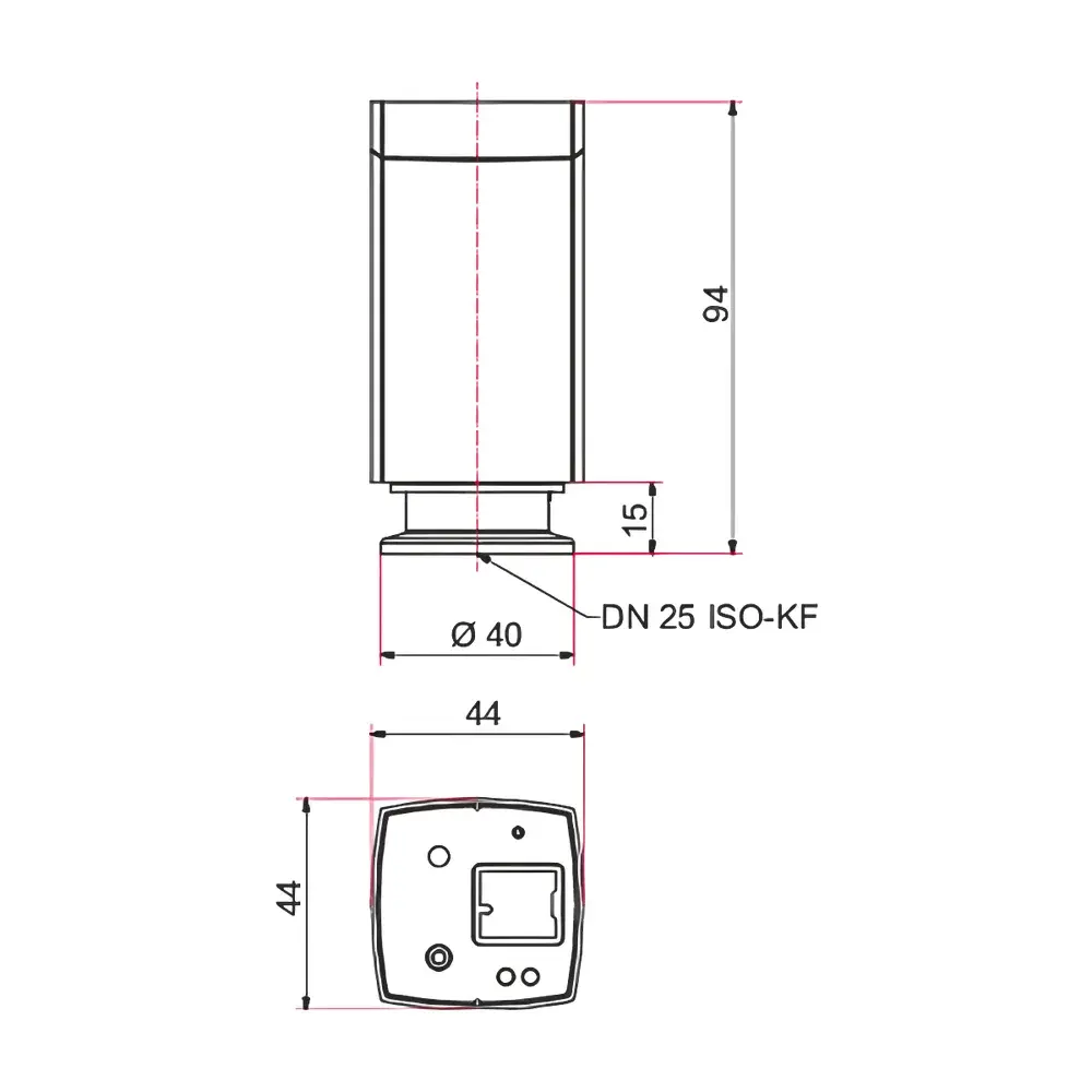
| Mounting | Anodized Aluminum Base with 4-40 and M4 threaded holes |
| Magnetic Coupling | Three Steel Ball Magnets for Quick Shear Plate Exchange |
| Reference Screen | Etched Scale Diffuser |
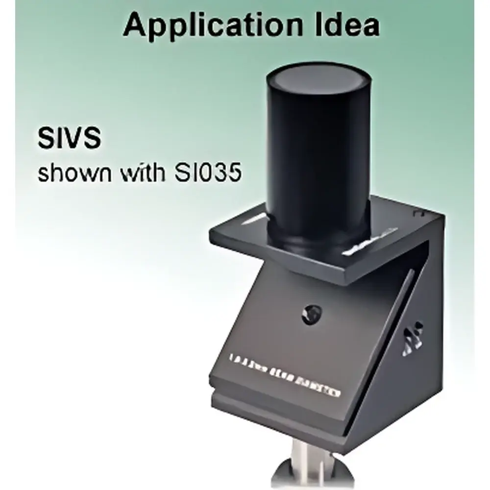
| Optional Accessory | SIVS Magnifying Viewing Screen (for Ø1–Ø10 mm beams) |
| Compliance | Designed for ISO 10110-7, ANSI Z80.10, and ASTM E1397-compliant optical alignment workflows |
Overview
The Thorlabs SI Series Shearing Interferometer is a precision optical alignment instrument engineered for rapid, qualitative assessment of laser beam collimation. Operating on the principle of lateral shearing interferometry, it introduces a controlled spatial offset—via a 45°-mounted wedge-shaped UV-fused silica plate—between two coherent wavefront replicas derived from front- and back-surface Fresnel reflections. The resulting interference fringes, observed on an integrated etched-scale diffuser screen, provide immediate visual feedback on beam divergence: parallel fringes aligned with the reference刻度 indicate collimation; curvature, tilt, or asymmetry reveals residual spherical aberration, coma, or astigmatism. Unlike quantitative phase-shifting interferometers, the SI Series delivers real-time, non-contact, zero-calibration verification ideal for laser cavity alignment, fiber coupling setup, and optical system commissioning in R&D and production environments. Its design prioritizes mechanical stability, polarization-aware contrast optimization (maximum fringe visibility at s-polarization), and compatibility with standard optomechanical infrastructure.
Key Features
- Magnetic shear plate retention system enables tool-free, repeatable exchange of five interchangeable wedge plates—each optimized for a specific beam diameter range (Ø1 mm, Ø3.5 mm, Ø5 mm, Ø10 mm, Ø25.4 mm, Ø50 mm)—ensuring minimal alignment drift across configurations.
- Anodized aluminum base integrates SM1 (1.035″-40) and 4-40 threaded mounting holes, supporting rigid integration into optical tables, kinematic mounts, and post-based systems while permitting unobstructed beam transmission through the rear aperture.
- Uncoated UV-fused silica shear plates exhibit high transmission (>90% @ 350–2000 nm) and low thermal expansion (α = 0.55 × 10⁻⁶ /°C), maintaining fringe stability under moderate power densities and ambient temperature fluctuations.
- Dual-function diffuser screen combines calibrated etched reference lines with Lambertian scattering properties, enabling both angular orientation assessment and fringe contrast evaluation without auxiliary optics.
- Compact, modular architecture—comprising base, shear plate carrier, and diffuser assembly—is supplied in a protective aluminum carrying case, facilitating field deployment and lab-to-lab transfer without recalibration.
Sample Compatibility & Compliance
The SI Series supports continuous-wave and pulsed lasers with coherence lengths exceeding the induced optical path difference (OPD) generated by the shear plate—typically ≥10 mm for standard configurations. It is compatible with visible, NIR, and UV sources (e.g., HeNe, diode, Ti:sapphire, and frequency-doubled Nd:YAG lasers), provided input polarization is controlled to maximize fringe contrast. The instrument conforms to foundational metrological practices outlined in ISO 10110-7 (surface irregularity assessment), ANSI Z80.10 (laser beam characterization), and ASTM E1397 (interferometric alignment procedures). While not a certified metrology standard, its repeatable qualitative output supports GLP-aligned optical alignment documentation when paired with controlled environmental conditions and operator training records.
Software & Data Management
The SI Series operates entirely without software or electronics—it is a passive, analog optical comparator. This eliminates firmware dependencies, driver conflicts, or cybersecurity vulnerabilities associated with digital instrumentation. Fringe interpretation follows standardized visual criteria documented in internal SOPs or external references such as SPIE PM122 (“Interferogram Analysis for Alignment”). For traceable recordkeeping, users may integrate the SI with third-party imaging systems (e.g., Thorlabs DCC1545M camera + Thorimage LS) to capture and archive fringe patterns. When used in regulated environments, image metadata (timestamp, operator ID, configuration ID) can be logged manually or via LIMS interfaces to satisfy FDA 21 CFR Part 11 audit-trail requirements for alignment verification steps.
Applications
- Laser cavity alignment and resonator mode optimization prior to output coupling.
- Verification of collimation after beam expanders, telescopes, or fiber collimator modules.
- Rapid screening of lens-induced wavefront errors during prototyping of imaging or illumination systems.
- Education and training in physical optics laboratories—demonstrating coherence, interference, and aberration sensitivity without complex setup.
- Pre-installation QA of free-space optical components (e.g., isolators, modulators) where beam divergence must remain within specification before integration.
FAQ
How does the SI Series distinguish between collimation error and other aberrations?
Fringe orientation relative to the etched scale indicates collimation (parallel = collimated); curvature radius reflects defocus; asymmetric bending indicates coma; orthogonal ellipticity suggests astigmatism.
Can the SI be used with femtosecond lasers?
Yes—if the laser’s coherence length exceeds the OPD introduced by the shear plate (typically ~5–15 µm for standard wedges), which is generally satisfied for <100 fs pulses centered at 800 nm.
Is polarization control required?
Optimal fringe contrast requires s-polarized light incident at 45°; p-polarized light yields significantly reduced visibility due to the Brewster effect at the UVFS interface.
What is the minimum measurable divergence angle?
Detection threshold depends on observer acuity and screen resolution but is typically ≤5 arcseconds for trained personnel using the standard diffuser; the optional SIVS magnifier improves resolution by ~3× for sub-5 mm beams.
Are calibration certificates available?
Thorlabs does not supply NIST-traceable calibration certificates for the SI Series, as it is a qualitative comparator—not a quantitative metrology device—though individual wedge angles are verified during manufacturing per ISO 10110-3 tolerances.