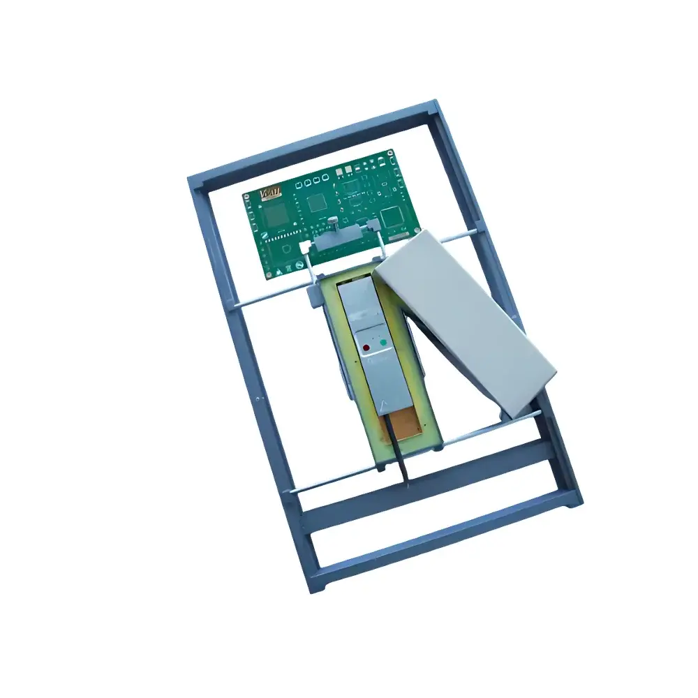
TTI LTX-5515 Analog Fiber-Optic Signal Transceiver
| Brand | TTI |
|---|---|
| Origin | USA |
| Model | LTX-5515 |
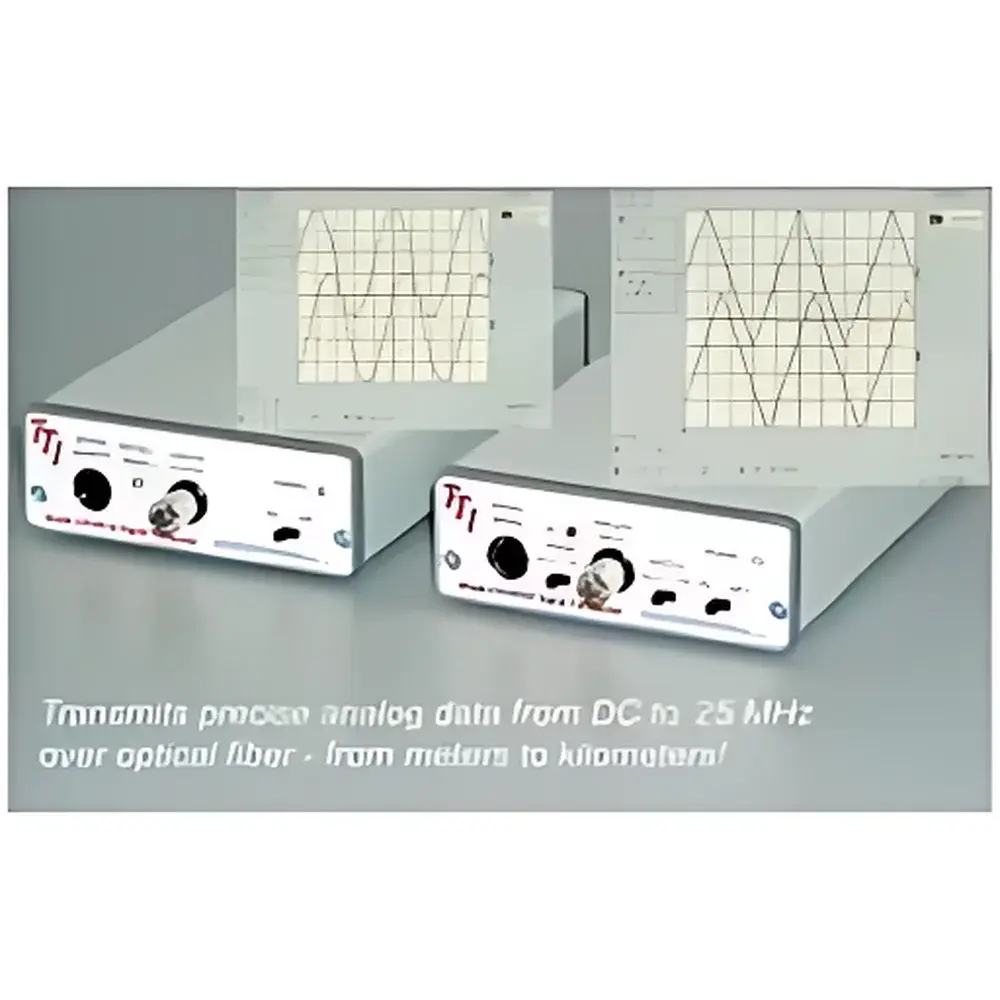
| Analog Bandwidth | DC–12.5 MHz (−3 dB) |
| Input Voltage Range | ±1 V or ±5 V |
| Resolution | 12-bit |
| Accuracy | ±0.1% Full Scale, ±20 mV offset |
| Max Data Rate | 50 Mb/s |
| Switching Speed | 0–12 MHz |
| Laser Wavelength | 850 nm ± 20 nm / 1310 nm ± 20 nm |
| Optical Interface | FC or ST |
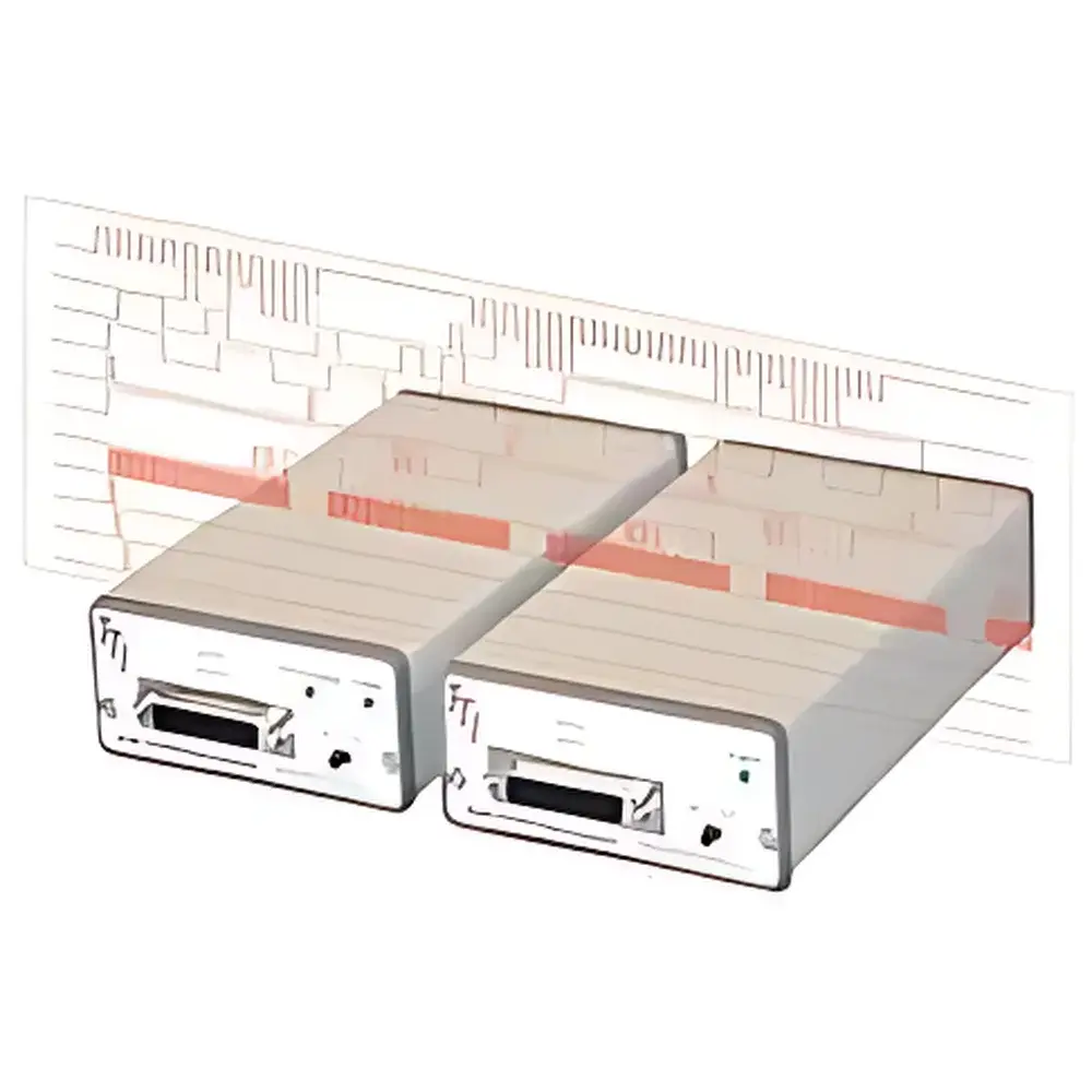
| Electrical Interface | DB25 |
| Compliance | RoHS, CE, UL Recognized |
Overview
The TTI LTX-5515 Analog Fiber-Optic Signal Transceiver is an engineered solution for high-fidelity, galvanically isolated transmission of analog voltage signals over optical fiber. Designed specifically for environments where electrical noise, ground loops, and high common-mode voltages pose critical measurement integrity risks—such as plasma diagnostics, high-voltage power electronics testing, and high-power laser monitoring—the LTX-5515 leverages intensity-modulated laser diode technology to convert analog input voltages into optical carriers, transmit them across multimode or single-mode fiber, and reconstruct the original signal with minimal distortion at the receiver end. Its core architecture implements linear current-to-light and light-to-current conversion using precision-calibrated photodiodes and transimpedance amplifiers, ensuring stable gain and low thermal drift across operating temperatures (0–60 °C). Unlike digital isolators or optocouplers, the LTX-5515 preserves analog bandwidth and dynamic range without quantization loss, making it suitable for real-time acquisition of fast transient waveforms in scientific and industrial instrumentation systems.
Key Features
- Galvanic isolation up to 5 kVRMS between electrical input/output and optical path, eliminating ground loop interference and enabling safe operation in high-common-mode-voltage scenarios (e.g., floating sensor nodes in plasma chambers or HVDC converter stations)
- Wide analog bandwidth of DC–12.5 MHz (−3 dB), supporting accurate reproduction of fast-rising pulses, RF-modulated envelopes, and broadband spectral content typical in laser pulse diagnostics and RF plasma impedance measurements
- High linearity and fidelity: 12-bit effective resolution, ±0.1% full-scale accuracy, and ±20 mV offset stability over temperature—validated per IEEE Std 1057 Annex B procedures
- Dual-wavelength compatibility (850 nm ± 20 nm and 1310 nm ± 20 nm) enables flexible deployment across both multimode (50/125 µm, 62.5/125 µm) and single-mode (9/125 µm) fiber infrastructures
- Robust mechanical design with FC or ST optical connectors and DB25 D-sub electrical interface, compliant with IEC 61000-4-3 (radiated immunity) and IEC 61000-4-4 (electrical fast transient) standards
- No external power supply required at the remote (transmitter) end when used with TTI’s matched LTR-series receivers—enabling passive sensor-side deployment in confined or hazardous locations
Sample Compatibility & Compliance
The LTX-5515 interfaces directly with standard analog output sensors and data acquisition systems delivering ±1 V or ±5 V unipolar/bipolar signals—including lock-in amplifier outputs, photodetector transimpedance stages, Rogowski coil integrators, and piezoelectric charge amplifiers. It is routinely deployed in ASTM E178-compliant test setups requiring traceable signal integrity under electromagnetic harshness (e.g., MIL-STD-461 RS103). The device conforms to RoHS Directive 2011/65/EU, carries CE marking per EMC Directive 2014/30/EU and Low Voltage Directive 2014/35/EU, and is UL Recognized under Component Recognition Service (E351924) for use in Class 1, Division 2 hazardous locations when installed per NEC Article 501. No FDA or ISO 13485 certification applies, as it is not a medical device component.
Software & Data Management
As a transparent analog signal conditioning and transport layer, the LTX-5515 operates independently of host software and requires no driver installation or firmware updates. It functions seamlessly with any DAQ platform—National Instruments PXI/USB systems, Keysight U2300A series, or custom LabVIEW, Python (PyVISA), or MATLAB-based acquisition frameworks. When integrated into GLP- or GMP-regulated environments, its deterministic latency (<150 ns group delay variation) and absence of internal buffering ensure compliance with FDA 21 CFR Part 11 requirements for raw data fidelity, provided the downstream DAQ system implements appropriate audit trail and electronic signature controls. Calibration certificates (NIST-traceable) are available upon request and include full-bandwidth frequency response sweeps and DC gain/offset characterization.
Applications
- Plasma physics experiments: Isolated acquisition of Langmuir probe I-V curves and microwave interferometer phase signals in tokamak and stellarator facilities
- Power electronics validation: Monitoring gate drive waveforms, snubber voltages, and current shunt outputs in SiC/GaN inverter stacks under switching frequencies exceeding 100 kHz
- High-energy laser metrology: Transmitting photodiode feedback signals from Q-switched Nd:YAG or fiber laser cavities while maintaining sub-nanosecond timing integrity
- EMC pre-compliance testing: Bridging near-field probe outputs to spectrum analyzers across shielded room boundaries without compromising measurement floor
- Aerospace avionics health monitoring: Remote analog telemetry from rotating machinery sensors (e.g., turbine vibration pickups) where slip rings introduce unacceptable noise
FAQ
Does the LTX-5515 support differential input signaling?
No—it accepts single-ended ±1 V or ±5 V inputs. For differential signal transmission, pair with a front-end instrumentation amplifier (e.g., TI INA149) prior to LTX-5515 input.
Can it be used with polarization-maintaining fiber?
Yes, though polarization sensitivity is negligible at 850 nm and 1310 nm due to the device’s intensity-modulation scheme; PM fiber may be used but offers no performance benefit.
Is recalibration required after field installation?
No—factory calibration remains valid over the specified operating temperature range; however, annual verification against a metrology-grade calibrator (e.g., Fluke 5520A) is recommended for ISO/IEC 17025-accredited labs.
What is the maximum allowable optical attenuation between transmitter and receiver?
Up to 15 dB for 850 nm operation and 22 dB for 1310 nm operation, assuming matched LTR-series receivers and standard launch conditions per IEC 61280-2-9.
Are spare optical modules or laser diodes user-replaceable?
No—optical assemblies are hermetically sealed and calibrated as a unit; field repair is not supported. Return-to-factory service is available for out-of-warranty units.