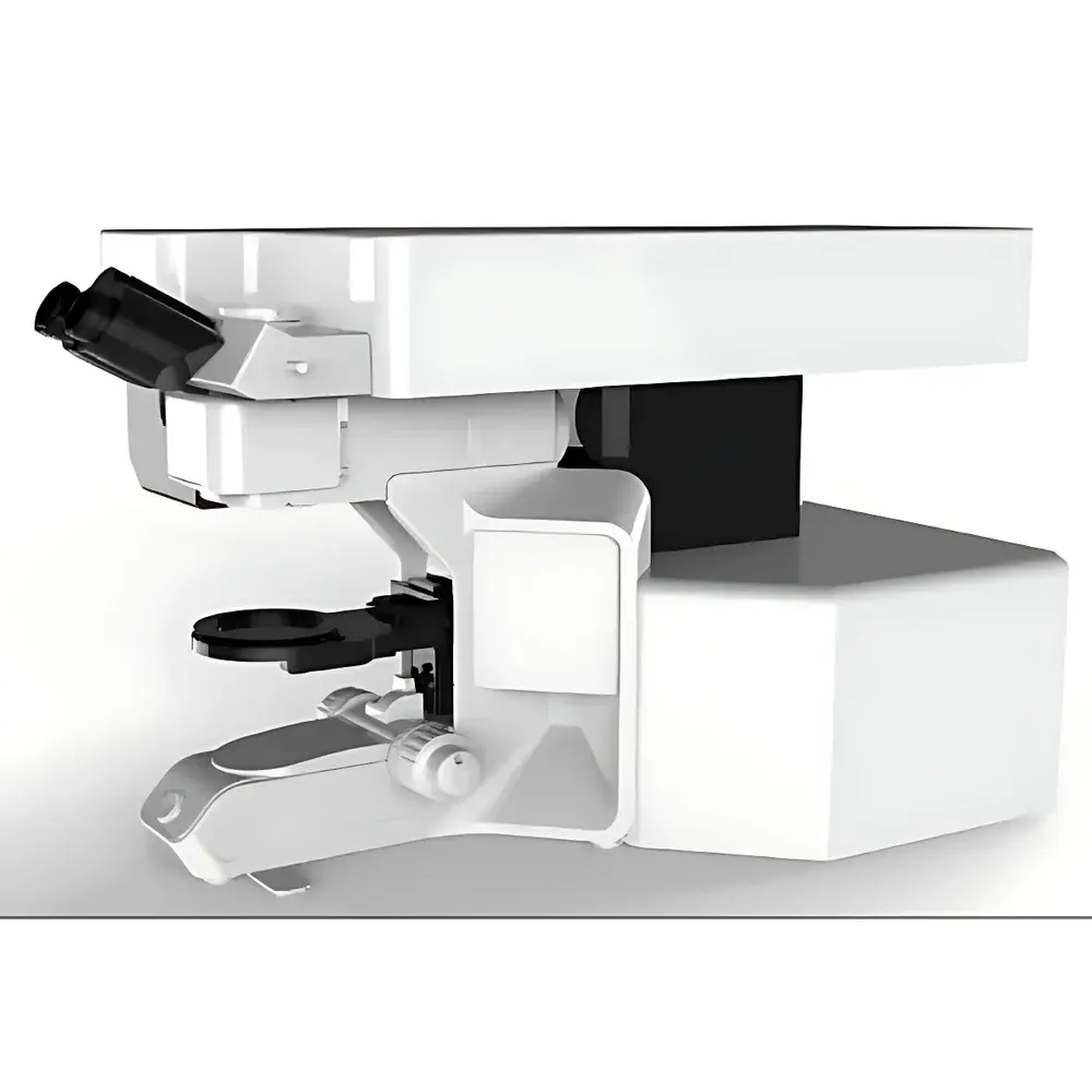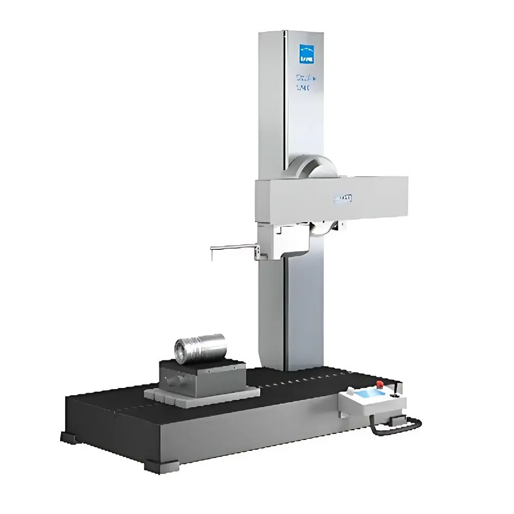
W900 High-Precision Desktop Profilometer
| Brand | Jenoptik |
|---|---|
| Origin | Germany |
| Model | W900 |
| Measurement Principle | Contact Stylus Profilometry with Dual-Axis Motorized Positioning |
| Vertical Resolution (Column with Linear Encoder) | 0.1 µm |
| Probe Compatibility | Nanoscan Stylus Sensors |
| Optional Accessories | Motorized Tilt Unit, Auto-Rotating Stylus Holder, Dual-Tip Probe Arm, Motorized Y-axis or X-Y Stage |
| CNC Programmability | Yes |
| Cylindrical Surface Measurement Capability | Axial & Circumferential Roughness Profiling |
| Compliance Framework | Designed for ISO 4287, ISO 4288, ISO 25178-2, and ASME B46.1 conformance |
Overview
The W900 High-Precision Desktop Profilometer is a modular, motorized contact profilometry system engineered by Jenoptik (Germany) for high-fidelity surface topography and roughness characterization in metrology laboratories and quality control environments. Built upon a rigid granite base and precision-machined mechanical architecture, the W900 employs a calibrated diamond-tipped stylus to trace surface profiles via controlled lateral (X) and vertical (Z) motion. Its core measurement principle adheres to the contact stylus method defined in ISO 3274 and ISO 4287, where vertical displacement of the probe is transduced via high-stability inductive or capacitive sensors, digitized at sub-nanometer resolution, and synchronized with high-accuracy linear encoders. The system’s vertical column integrates a precision optical grating scale with 0.1 µm resolution—enabling accurate Z-axis positioning beyond the native range of the sensor head—making it suitable for step-height measurements, form error analysis, and multi-scale profiling of complex geometries including freeform surfaces and micro-structured components.
Key Features
- Modular dual-probe configuration: Primary Nanoscan stylus sensor mounted on the main carriage; secondary roughness probe integrated at the front of the drive unit for rapid switching between form and finish assessment.
- Motorized tilt unit (optional): Enables precise angular alignment of the stylus relative to the workpiece plane—critical for measuring inclined surfaces, tapered features, or anisotropic textures while maintaining consistent tip–surface contact geometry.
- CNC programmability: Full G-code compatibility allows automated execution of multi-point, multi-region, or multi-angle measurement routines—including repeated scans across cylindrical parts in both axial and circumferential directions.
- Enhanced positioning capability: Optional motorized Y-axis or X-Y stage facilitates automatic peak/valley search, edge detection, and precise workpiece centering—reducing operator dependency and improving repeatability in batch inspection.
- Dual-tip probe arm support: Accommodates specialized probe arms with two interchangeable stylus tips (e.g., 2 µm and 5 µm radius), enabling seamless transition between fine-detail roughness evaluation and robust form measurement without manual recalibration.
- Thermal and vibration stability: Granite baseplate, air-damped isolation feet, and low-thermal-drift mechanical design ensure long-term measurement consistency under ambient laboratory conditions (20 ± 1 °C, <50% RH).
Sample Compatibility & Compliance
The W900 accommodates flat, curved, and rotationally symmetric samples up to Ø300 mm × 100 mm height (standard configuration); extended stages support larger substrates upon customization. It is routinely deployed for characterizing machined metal surfaces, polished optical components, semiconductor wafers, medical implants, and additive-manufactured parts. All measurement algorithms and reporting outputs comply with international standards including ISO 4287 (roughness parameters), ISO 4288 (lay and waviness assessment), ISO 25178-2 (areal surface texture), and ASME B46.1. Raw data files are timestamped and include full metadata (probe type, scan speed, filter settings, calibration ID), supporting GLP/GMP audit requirements and FDA 21 CFR Part 11–compliant electronic record workflows when paired with validated software modules.
Software & Data Management
Controlled via Jenoptik’s proprietary WinRough+ software suite, the W900 provides intuitive graphical interface for real-time profile visualization, filter selection (Gaussian, Spline, Robust Gaussian), parameter calculation (Ra, Rz, Rq, Rsk, Rku, Rmr, etc.), and customizable report generation (PDF, CSV, XML). The software supports script-based automation through COM interface, integration with MES/QMS platforms via OPC UA, and secure user-role management (administrator, operator, reviewer). All measurement sessions are logged with digital signatures, change history, and version-controlled calibration certificates—ensuring full traceability from acquisition to final certification.
Applications
- Quantitative verification of surface finish after grinding, lapping, EDM, or laser texturing processes.
- Form deviation analysis of precision shafts, bearing races, and sealing surfaces per ISO 1101.
- Waviness separation and functional correlation studies for tribological performance prediction.
- Quality gate inspection in aerospace turbine blade manufacturing and automotive cylinder bore production.
- Research-grade surface characterization in academic labs studying wear mechanisms, coating adhesion, or bio-interface topography.
FAQ
Does the W900 support non-contact measurement modes?
No—the W900 is a dedicated contact profilometer. For non-contact alternatives, Jenoptik offers complementary white-light interferometry (WLI) and confocal chromatic systems.
Can the system measure inside small-diameter bores?
Standard probe configurations are limited to external or open-surface scanning. Specialized narrow-profile stylus holders and articulated probe arms are available as custom options for restricted-access geometries.
Is ISO/IEC 17025 calibration documentation included?
Factory calibration certificates per ISO/IEC 17025 are provided with each system shipment; accredited third-party calibration services can be arranged separately.
What is the typical measurement speed range?
Scan speeds are adjustable from 0.1 µm/s to 5 mm/s, optimized based on required lateral resolution, surface slope, and noise tolerance—typically 0.5–2 mm/s for routine Ra/Rz evaluation.
How is thermal drift compensated during extended measurements?
The system incorporates real-time temperature monitoring at critical mechanical nodes; software applies empirically derived compensation coefficients derived from long-term stability testing under controlled environmental conditions.