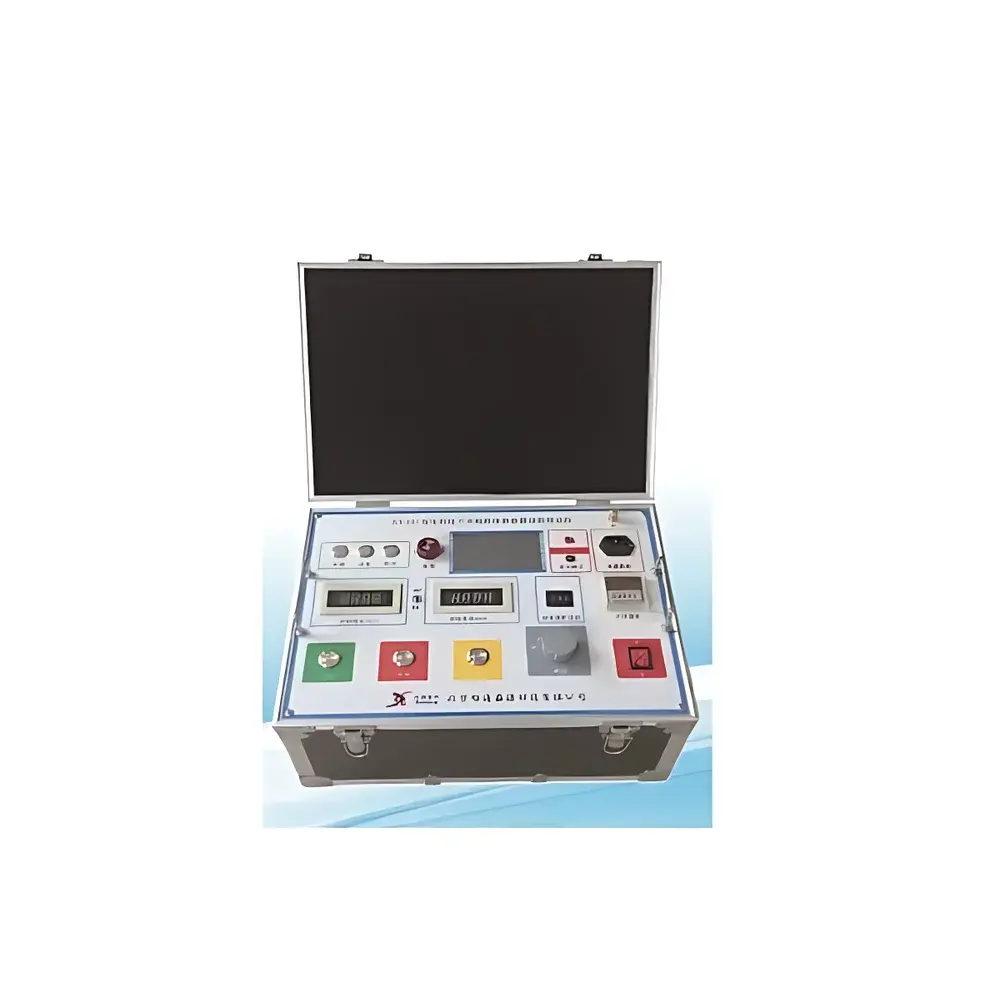
Xutongyongfu XT-107A Generator Rotor Overvoltage Protection Device Tester
| Brand | Xutongyongfu |
|---|---|
| Model | XT-107A |
| Origin | Beijing, China |
| Power Supply | AC 220 V ±10%, 50 Hz ±1 Hz |
| Operating Temperature | −5 °C to +40 °C |
| Relative Humidity | ≤90% at +25 °C |
| Output Voltage Rating | DC 4.5 kV / AC 3 kV |
| Accuracy | ±1.5% |
| Rated Capacity | 2 kVA |
| Dimensions | 400 × 300 × 300 mm |
| Display | 4½-digit digital meters + embedded oscilloscope module |
| Safety Features | Zero-position interlock, overcurrent protection, timed audible/visual alarm |
| Input–Output Isolation | Galvanically isolated |
| Output Configuration | Rear-panel high-voltage AC/DC terminals |
Overview
The Xutongyongfu XT-107A Generator Rotor Overvoltage Protection Device Tester is a purpose-built diagnostic instrument engineered for the functional verification and performance validation of rotor overvoltage suppression systems—specifically magnetic blowout (de-excitation) arresters and thyristor-based cross-connectors installed in large turbo-generators. It operates on the principle of controlled high-voltage stress application to simulate transient overvoltage events that occur during abnormal shutdowns, field winding faults, or external grid disturbances. By replicating realistic voltage surges—including both AC and DC components—the XT-107A enables quantitative assessment of arrester conduction thresholds, thyristor firing angles, clamping behavior, and energy absorption capacity under defined test conditions compliant with DL/T 843–2010. This instrument supports routine commissioning, periodic maintenance, and post-repair validation in accordance with national technical specifications for static excitation systems in thermal power plants.
Key Features
- Galvanically isolated input–output architecture ensures operator safety and eliminates ground-loop interference during high-voltage testing.
- Dual-mode high-voltage output: independently configurable AC (up to 3 kVrms) and DC (up to 4.5 kV) sources mounted on rear panel for ergonomic separation from operator interface.
- Integrated 4½-digit digital voltmeter and ammeter with rotary selector switch for rapid channel switching between voltage, current, and auxiliary measurement modes.
- Embedded real-time oscilloscope module displays dynamic waveforms of thyristor gate triggering, conduction onset, and voltage clamping characteristics—critical for evaluating response time and symmetry in bidirectional arresters.
- Zero-position mechanical interlock prevents inadvertent high-voltage activation; automatic overcurrent cutoff halts output within <100 ms upon threshold breach.
- Timed audible–visual alarm system provides programmable warning intervals prior to test completion or fault detection, supporting documented procedural adherence.
- Manual ramp-up control with fine-resolution voltage regulation allows stepwise stress application aligned with DL/T 843–2010 test sequences.
Sample Compatibility & Compliance
The XT-107A is designed for direct connection to generator rotor circuits equipped with solid-state cross-connectors (e.g., thyristor stacks), ZnO varistor arrays, or hybrid de-excitation arresters. It accommodates standard field winding insulation classes (B, F, H) and interfaces with common excitation cabinet terminal blocks via insulated HV cables rated ≥10 kV. The instrument conforms to the electrical safety requirements outlined in GB/T 4793.1–2018 (equivalent to IEC 61010-1) for measurement, control, and laboratory equipment. Its test methodology directly implements Clause 6.4.3 (“Rotor Overvoltage Test”) of DL/T 843–2010, including specified waveform rise times, peak amplitude tolerances, and minimum dwell durations. While not certified to ISO/IEC 17025, its measurement uncertainty budget (±1.5% at full scale) meets traceability requirements for in-service verification per utility internal QA protocols.
Software & Data Management
The XT-107A operates as a standalone hardware tester without embedded firmware-based automation or PC connectivity. All measurements are captured in real time via analog-to-digital conversion and rendered locally on the front-panel digital display and integrated oscilloscope screen. Waveform data from the oscilloscope module is non-storage-capable but supports visual interpretation and manual annotation during live testing. Users are expected to document results—including conduction angle values, clamping voltage plateaus, and time-to-trigger metrics—in accordance with plant-specific maintenance records or ISO 9001-compliant work packages. For laboratories requiring electronic audit trails, external digital oscilloscopes with USB export or calibrated data loggers may be synchronized using the instrument’s trigger output signal.
Applications
- Periodic functional testing of rotor overvoltage protection devices during scheduled generator outages.
- Commissioning verification after installation of new excitation systems or replacement of cross-connector modules.
- Troubleshooting unexplained rotor insulation degradation by correlating arrester response anomalies with historical surge exposure.
- Validation of thyristor firing consistency across multi-unit parallel configurations in dual-channel excitation cabinets.
- Supporting root-cause analysis following forced outages attributed to field winding failure or flashover incidents.
- Training technicians on safe high-voltage test procedures while maintaining strict separation between HV zones and control interfaces.
FAQ
Does the XT-107A support automated test sequencing per DL/T 843–2010?
No—it requires manual voltage ramping and operator-initiated measurement recording, consistent with field-deployable test set conventions.
Can the oscilloscope module store waveforms for later review?
No; it provides real-time visualization only. External capture is required for archival purposes.
Is calibration traceable to national standards?
Yes—primary voltage and current sensors are factory-calibrated against CNAS-accredited reference standards, with certificate provided upon delivery.
What protective measures prevent accidental energization?
Mechanical zero-position interlock, illuminated HV status indicator, and mandatory key-switch enable sequence collectively enforce procedural safety.
Does the instrument comply with electromagnetic compatibility (EMC) requirements for substation environments?
It meets Class B emission limits per GB 9254–2008 (CISPR 22) and withstands conducted disturbances up to 2.5 kV per IEC 61000-4-4, verified via third-party EMC report.


