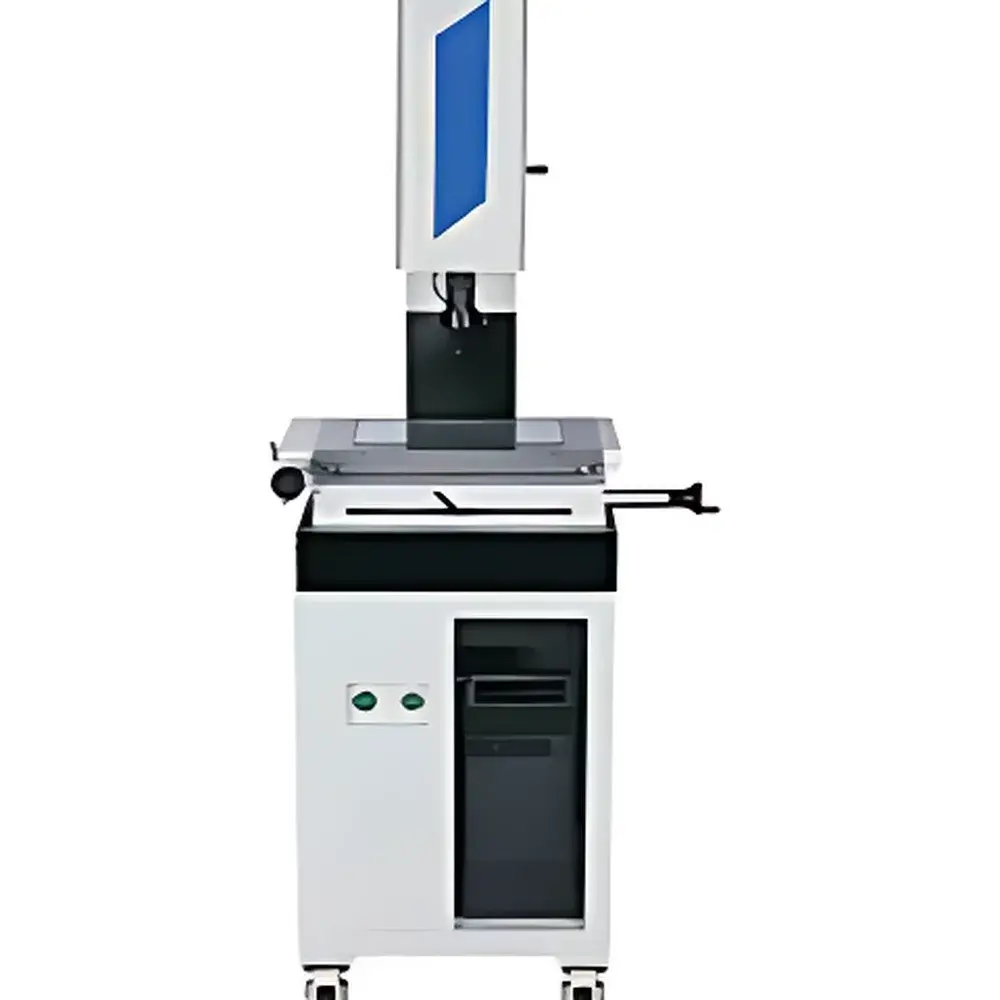
YANRUN YR2010S Manual 2D Video Measuring System
| Brand | YANRUN |
|---|---|
| Origin | Shanghai, China |
| Manufacturer Type | Direct Manufacturer |
| Product Origin | Domestic (China) |
| Model | YR2010S |
| Operation Mode | Manual |
| Measurement Accuracy | ±(3 + L/200) µm |
| Encoder Resolution | 1 µm |
| Lens | 0.7×–4.5× High-Definition Continuous Zoom Objective |
| Illumination | Closed-loop LED Coaxial & Ring Light System |
| Scale Type | Precision Glass Linear Encoder with 1 µm Resolution |
Overview
The YANRUN YR2010S Manual 2D Video Measuring System is an entry-level precision coordinate metrology instrument engineered for non-contact geometric inspection of planar features on machined parts, tooling components, and small-scale industrial assemblies. It operates on the principle of optical magnification and digital edge detection: a high-resolution monochrome or color camera—coupled with a continuously variable zoom lens (0.7× to 4.5×)—captures real-time images of the part placed on the precision granite stage. Geometric features—including points, lines, circles, arcs, distances, angles, and profiles—are measured by operator-guided cursor placement or automated edge-finding algorithms within the integrated measurement software. The system employs a closed-loop illumination architecture with coaxial and ring-light configurations to optimize contrast across reflective, matte, and semi-transparent surfaces. Its core motion feedback is provided by glass linear encoders with 1 µm resolution, mounted directly on each axis (X and Y), ensuring traceable positional repeatability under ambient laboratory conditions.
Key Features
- Manual operation platform with ergonomic handwheel controls for precise X/Y stage movement and Z-axis focus adjustment
- Precision granite base and column structure providing thermal stability and mechanical rigidity over extended measurement cycles
- High-fidelity optical path incorporating a 0.7×–4.5× continuous zoom lens with parfocal design—enabling seamless magnification changes without refocusing
- Dual-mode illumination system: adjustable coaxial LED for surface texture analysis and programmable ring light for contour edge enhancement
- Integrated 1 µm-resolution glass linear encoders on both X and Y axes, certified per ISO 230-2 for positioning accuracy and repeatability
- Real-time on-screen coordinate display with support for Cartesian, polar, and user-defined coordinate systems
- Multi-point sampling capability with automatic best-fit calculation for circles, lines, and arcs per ISO 1101 geometric tolerancing standards
Sample Compatibility & Compliance
The YR2010S accommodates workpieces up to 200 mm × 100 mm × 100 mm (W × D × H), with maximum weight capacity of 15 kg. It is routinely deployed for dimensional verification of stamped sheet metal parts, injection-molded plastic housings, watch movement components, PCB stencils, electrical terminals, and cutting tools such as end mills and gear hobs. The system complies with fundamental metrological requirements outlined in ISO/IEC 17025 for calibration laboratories and supports GLP-aligned documentation workflows. While not certified to full ISO 10360-7 (CMM performance verification), its stated accuracy of ±(3 + L/200) µm aligns with Class MPE (Maximum Permissible Error) expectations for manual vision-based measuring instruments per VDI/VDE 2634 Part 2 guidelines.
Software & Data Management
The embedded measurement software provides bilingual UI (English/Chinese) with intuitive icon-driven navigation. All measurements are timestamped and stored in structured XML format, supporting export to CSV, DXF, and PDF reports. RS-232 serial interface enables direct communication with external SPC platforms or legacy MES systems. CAD import functionality accepts standard 2D DXF files for overlay-based deviation analysis—allowing users to compare actual part contours against nominal geometry. Audit trail logging is available for critical operations (e.g., calibration updates, user login/logout, report generation), meeting baseline data integrity requirements under FDA 21 CFR Part 11 when configured with user authentication and electronic signature protocols.
Applications
- First-article inspection of prototype tooling and die sets in mold-making workshops
- Dimensional validation of micro-electromechanical system (MEMS) substrates and connector pins
- Profile matching of cam lobes, gear tooth forms, and thread-forming taps against master templates
- Geometric tolerance assessment—including position, concentricity, and profile of a line—per ASME Y14.5 and ISO GPS standards
- QC gate inspection for high-volume production of consumer electronics housings and automotive sensor brackets
- Educational use in metrology training labs for foundational concepts in coordinate measurement and GD&T interpretation
FAQ
What is the maximum field of view at lowest and highest magnification?
At 0.7× zoom, the approximate FOV is 12.8 mm × 9.6 mm; at 4.5×, it reduces to ~2.0 mm × 1.5 mm—both values dependent on sensor size and pixel binning configuration.
Does the system support automatic edge detection?
Yes—the software includes threshold-based and gradient-based edge search algorithms, configurable by sensitivity and noise rejection parameters.
Can measurement data be exported to statistical process control (SPC) software?
Yes, via ASCII-formatted CSV output or real-time streaming through RS-232, compatible with common SPC packages including Minitab, InfinityQS, and WinSPC.
Is calibration certification included with purchase?
A factory calibration report (traceable to NIM China) is supplied; optional UKAS-accredited calibration services are available upon request.
What environmental conditions are recommended for optimal performance?
Operating temperature: 20 ± 2 °C; relative humidity: 40–60% RH; vibration isolation recommended per ISO 22989 for sub-5 µm uncertainty applications.