VICI VISION M609 TECHINO Fully Automatic Non-Contact Optical Shaft Measurement System
| Origin | Italy |
|---|---|
| Supplier Type | Authorized Distributor |
| Origin Category | Imported |
| Model | M609 TECHINO |
| Pricing | Upon Request |
Overview
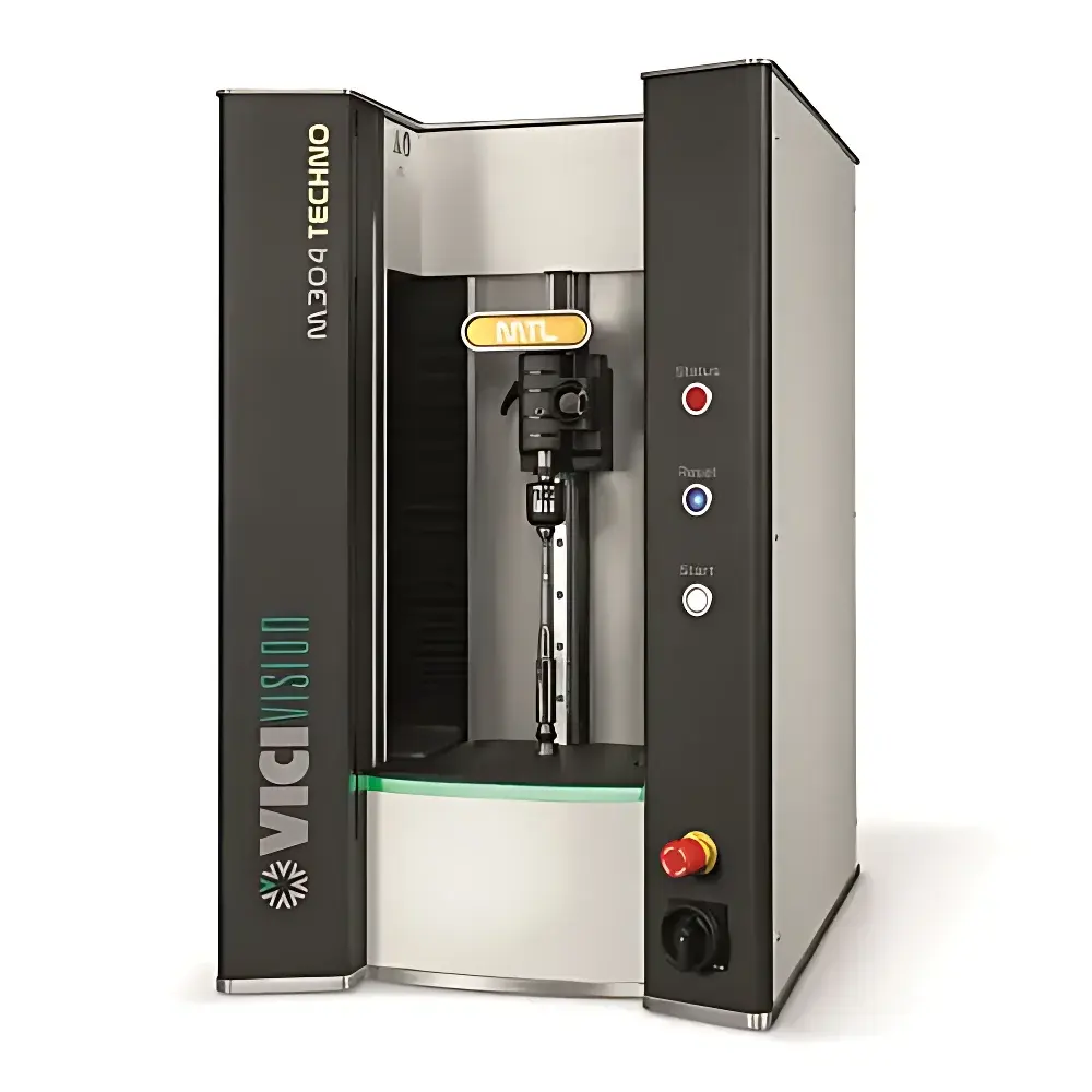
The VICI VISION M609 TECHINO is a fully automatic, non-contact optical shaft measurement system engineered for high-precision geometric metrology of rotating cylindrical components—particularly drive shafts, transmission shafts, and other rotationally symmetric mechanical parts. It operates on the principle of telecentric imaging combined with high-resolution linear CCD acquisition, enabling full-field vertical scanning and synchronized rotational profiling. Unlike tactile CMMs or manual micrometer-based methods, this system eliminates mechanical contact, thermal drift, and operator-induced deformation—critical for maintaining integrity during in-process inspection of hardened, ground, or heat-treated shafts. Designed for integration directly beside CNC machine tools, it supports shop-floor deployment under ISO 14644 Class 8 (ISO Class 100,000) ambient conditions, with sealed enclosure architecture and large front access to minimize particulate ingress while enabling ergonomic two-hand loading/unloading. Its structural rigidity—achieved through aluminum monocoque frame with reinforced ribs—and vibration-damped vertical motion system ensure sub-micron stability during dynamic rotational scanning of parts up to 30 kg.
Key Features
- Telecentric dual-lens optical path: One telecentric illumination lens and one telecentric imaging lens, ensuring constant magnification across depth of field (DOF) and eliminating perspective error for true dimensional fidelity.
- Motorized vertical scanning axis: Brushless DC servo drive with 80 mm/s maximum speed and sub-5 µm positional repeatability; integrated with linear encoder feedback for traceable vertical positioning.
- Rotational axis: High-torque brushless motor with 180°/s max speed and programmable acceleration/deceleration profiles; supports continuous rotation or indexed angular stops at user-defined intervals (e.g., cam lobe sampling).
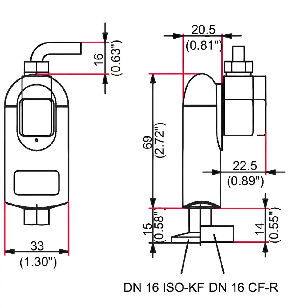
- Ergonomic tailstock design: Upper tailstock features Morse taper MT2 (60° external cone), vertical rack-and-pinion adjustment with counterbalance system, and precision <0.003 mm runout specification; lower fixed tailstock matches identical taper geometry.
- Step-Master onboard thermal stabilization module: Actively monitors and compensates for ambient temperature fluctuations in real time, synchronizing image acquisition timing and dimensional correction algorithms.
- Dust-resistant enclosure: Front-opening large-access aperture with gasketed top cover; optimized airflow management prevents accumulation of metal chips or coolant mist without requiring forced ventilation.
Sample Compatibility & Compliance
The M609 TECHINO accommodates shafts with maximum dimensions of 625 mm length × 120 mm diameter and mass up to 30 kg. Its standard V-block set (6–35 mm groove width) and Morse taper centers (1–18 mm range) support rapid setup for both small-diameter precision spindles and large-diameter driveline components. The system complies with fundamental metrological requirements outlined in ISO 10360-2 (CMM performance verification) and ISO 14253-1 (geometrical product specifications — decision rules). While not certified to full GLP/GMP validation protocols out-of-the-box, its software architecture supports audit-ready data logging—including timestamped operator ID, environmental readings, and calibration certificate references—enabling alignment with FDA 21 CFR Part 11 when deployed in regulated manufacturing environments. All mechanical interfaces meet ISO 2768-mK general tolerancing standards for workshop equipment mounting.
Software & Data Management
The proprietary VICI VISION measurement software runs on Windows 10 Professional (64-bit) and provides a graphical, icon-driven interface for program creation, execution, and reporting. Measurement routines are generated via point-and-click workflow: users define reference geometry (e.g., datum axes, base planes) directly on live images, then assign measurement types (diameter, roundness, thread pitch, conicity, etc.) with configurable tolerance zones per GD&T symbol. The software implements least-squares circle (LSC), minimum inscribed circle (MIC), maximum inscribed circle (MCC), and minimum zone circle (MZC) algorithms for form analysis. All raw image frames, coordinate datasets, and statistical summaries (Cp/Cpk, Pp/Ppk) are stored in encrypted binary format with optional export to CSV, PDF, or XML for SPC integration. Audit trail functionality logs every parameter change, measurement trigger, and report generation event—including IP address, Windows login credentials, and system clock synchronization status—meeting baseline requirements for ISO/IEC 17025-compliant laboratories.
Applications
This system is routinely deployed in Tier-1 automotive powertrain facilities for inline verification of CV joint shafts, differential pinions, and turbocharger spindles; in aerospace MRO workshops for turbine shaft concentricity and bearing journal roundness assessment; and in precision gear manufacturing for flank profile and lead deviation screening prior to hobbing or grinding. Specific use cases include: automated detection of grinding burn-induced surface distortion via local diameter variance mapping; multi-angle cam lobe profiling with synchronous angular position tagging; thread form evaluation on splined couplings using cross-sectional slice reconstruction; and coaxiality verification between multiple bearing journals separated by >500 mm. Its ability to perform complete geometric characterization—including cylindricity, circular runout, total runout, and angular position of keyways—in under 90 seconds per part makes it suitable for 100% final inspection in high-volume production cells.
FAQ
What is the maximum measurable shaft length and diameter?
The system supports parts up to 625 mm in length and 120 mm in diameter, with full-field optical coverage across a 600 mm × 90 mm measurement envelope.
Does the system require environmental climate control?
While optimal performance is specified at 20 °C ± 1 °C, the Step-Master thermal compensation system enables stable operation within 15–25 °C ambient ranges without recalibration.
Can the software generate ASME Y14.5-compliant GD&T reports?
Yes—tolerance zones, datum references, and feature control frames are defined graphically and exported with full GD&T annotation in PDF reports.
Is calibration traceability provided?
Each unit ships with a factory calibration certificate traceable to NIST via accredited Italian metrology labs (UNI CEI EN ISO/IEC 17025), including uncertainty budgets for diameter and length measurements.
What maintenance is required for long-term accuracy?
Annual verification of optical alignment and encoder linearity is recommended; no routine lubrication or mechanical adjustment is needed due to brushless motor and sealed linear guide design.