DesTest DS TS-TG12000 Tracking Signal Generator
| Key | Brand: DS Instruments |
|---|---|
| Origin | USA |
| Model | TS-TG12000 |
| Frequency Range (Tracking Mode) | DC–12 GHz (3 bands: 0–2.5 GHz, 2.0–5.8 GHz, 5.8–12 GHz) |
| Frequency Range (Standalone RF Source) | 25–6000 MHz |
| Typical TG Output Power | –3 dBm (Bands 1 & 2), –8 dBm (Band 3) |
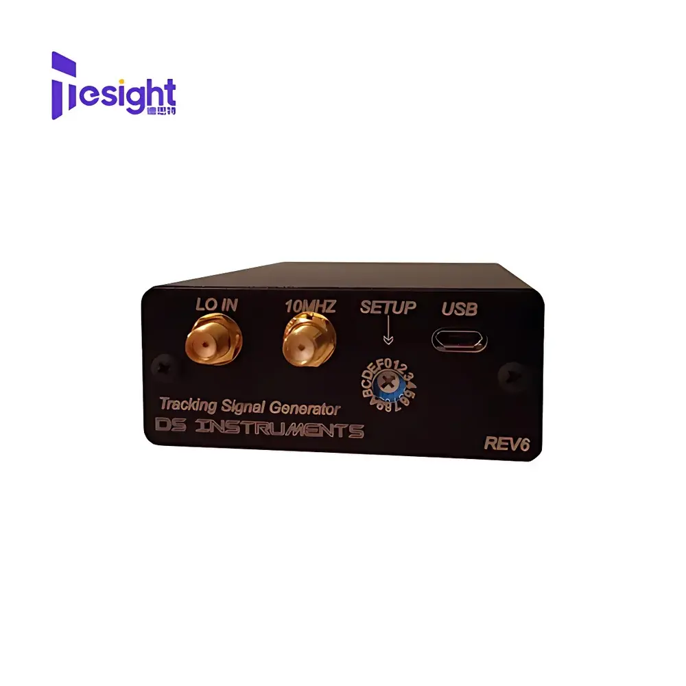
| Reference Input | 10 MHz via SMA |
| Power Supply | USB-powered (5 VDC) |
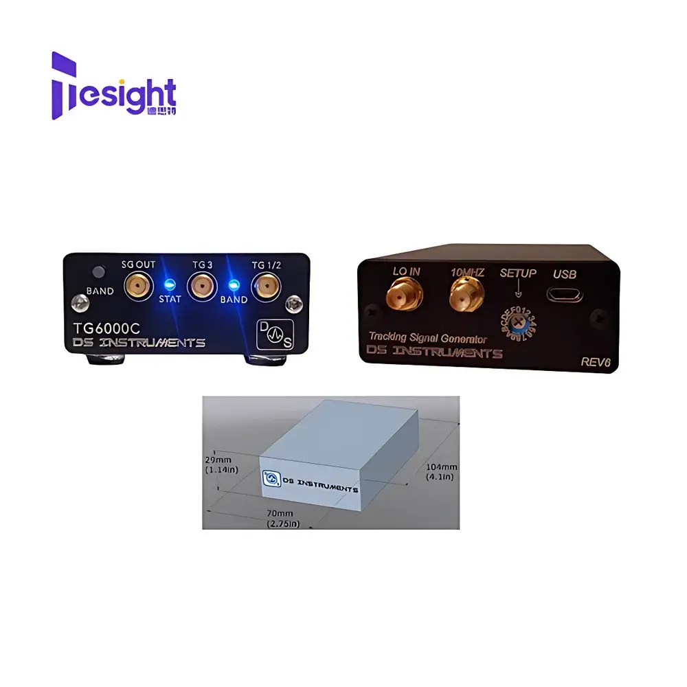
| Enclosure | Machined aluminum |
| Connectors | SMA (front), MCX (rear), USB-B |
| Control Interface | USB Virtual COM port, SCPI-compliant |
| Dimensions | 2.75" × 4.15" × 1.15" (70 × 105 × 29 mm) |
| Compliance | CE, FCC Part 15 Class B |
| Software | Windows-based PC control application included |
Overview
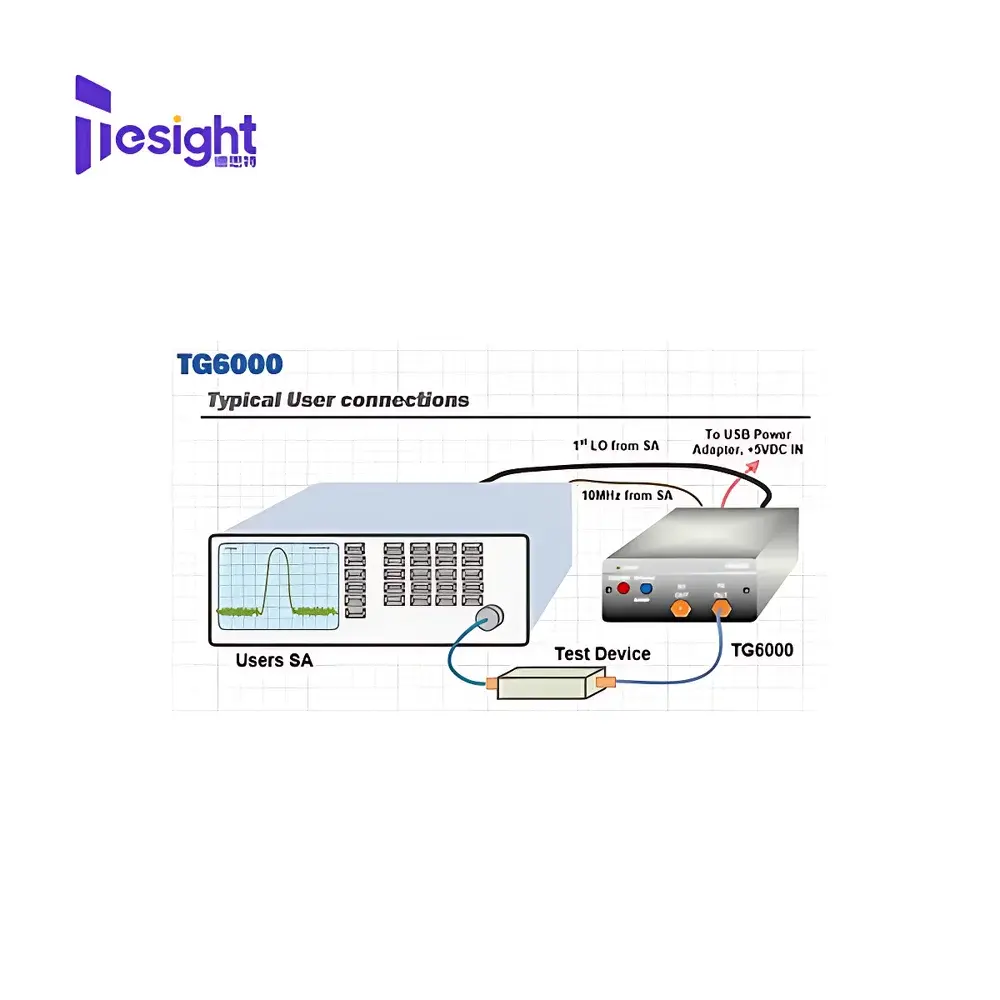
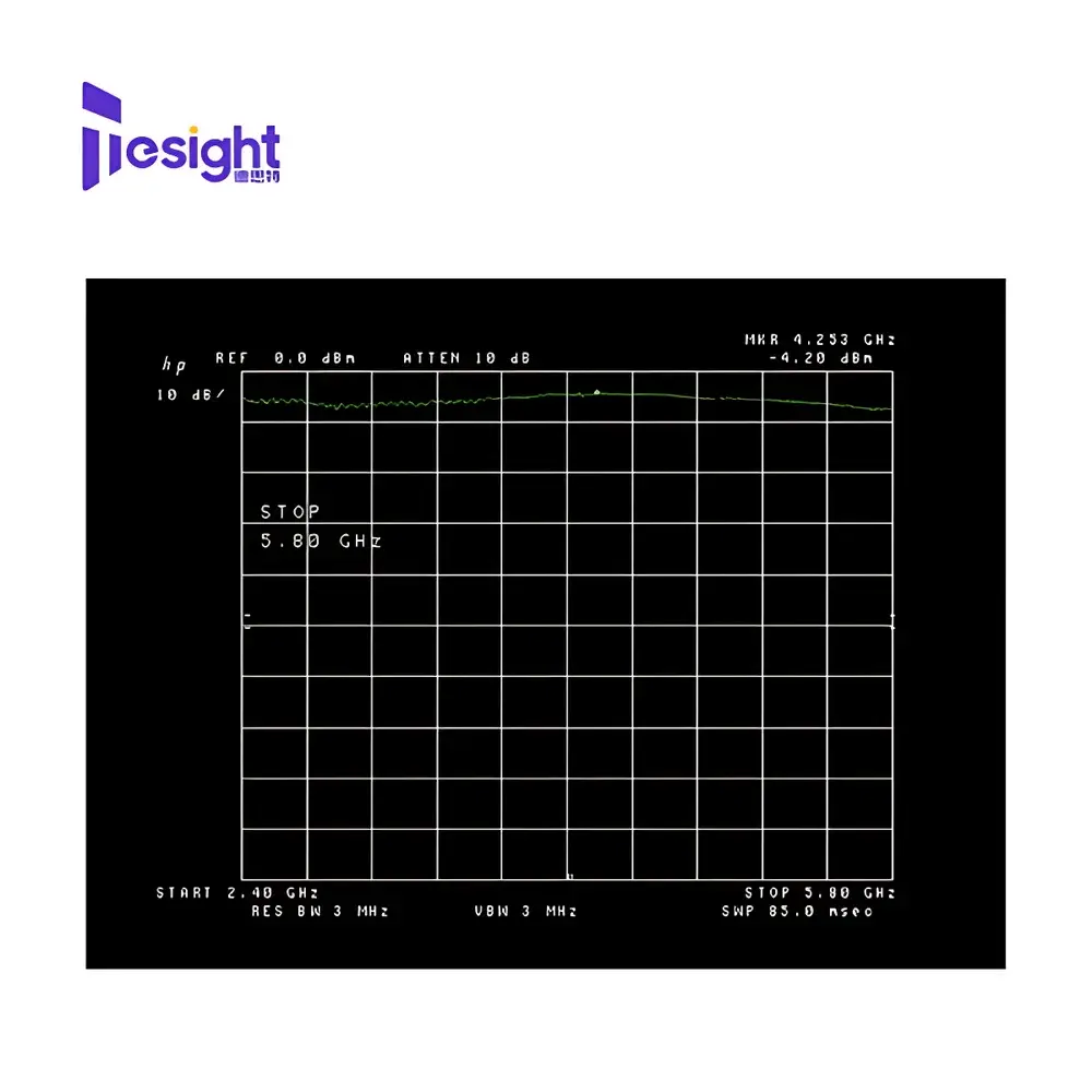
The DesTest DS TS-TG12000 is a precision-engineered tracking signal generator designed for high-fidelity characterization of passive and active RF components in laboratory, production test, and field service environments. Operating on the principle of synchronous swept-frequency stimulus-response measurement, the TS-TG12000 delivers phase-coherent RF output synchronized to the sweep of a compatible spectrum analyzer—enabling real-time, normalized insertion loss, return loss, and group delay measurements of filters, duplexers, cables, attenuators, and amplifiers. Unlike fixed-frequency sources, its three-band tracking architecture (0–2.5 GHz, 2.0–5.8 GHz, and 5.8–12 GHz) ensures seamless coverage across the full 12 GHz span without manual band switching or calibration gaps. When used standalone—as a calibrated RF source—the instrument provides continuous-wave output from 25 MHz to 6 GHz, making it suitable for local oscillator substitution, receiver sensitivity testing, and basic modulation verification.
Key Features
- Triple-band tracking operation (DC–12 GHz) with automatic band transition and amplitude normalization
- Standalone RF signal generation capability (25–6000 MHz) with user-selectable CW or swept modes
- USB-powered architecture eliminates external power supplies and enhances portability
- Machined aluminum enclosure provides EMI shielding, thermal stability, and mechanical robustness for benchtop and rack-mounted deployment
- Full SCPI command set compliant with IEEE 488.2 and LXI-C standards for integration into automated test systems (ATE)
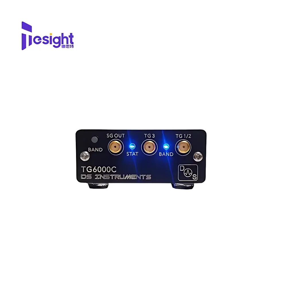
- Dual front-panel SMA outputs: one for tracking reference path, one for device-under-test stimulation
- 10 MHz reference input (SMA) supports phase-locking to external master clocks or system synchronizers
- Status LEDs and audible tone feedback enable rapid visual/auditory confirmation of operational state and sweep synchronization
- PC control software includes sweep parameter configuration, trace export (CSV, S2P), and batch logging for GLP/GMP-aligned documentation
Sample Compatibility & Compliance
The TS-TG12000 is engineered for interoperability with industry-standard spectrum analyzers—including Keysight (formerly Agilent) ESA/E44xx, FieldFox, and X-Series; Rohde & Schwarz FSW/FPS; Tektronix RSA; and Anritsu MS20xx series—via standard IF/trigger and sweep synchronization protocols. Its output impedance (50 Ω), VSWR (<1.5:1), and harmonic suppression (>40 dBc typical) meet requirements for accurate scalar network analysis per IEEE Std 145-2013 and IEC 61000-4-3. The device complies with FCC Part 15 Subpart B (Class B digital device) and EU Directive 2014/53/EU (RED), bearing CE marking. Its firmware architecture supports audit-ready logging and timestamped event records, facilitating alignment with ISO/IEC 17025-accredited lab workflows and FDA 21 CFR Part 11 electronic record controls when paired with validated host software.
Software & Data Management
The bundled Windows application provides intuitive GUI-based control of all instrument functions—including start/stop frequency, RBW coupling, sweep time, output level, and trigger mode—without requiring low-level SCPI scripting. Trace data can be exported in industry-standard formats: CSV for spreadsheet analysis, Touchstone (.s1p/.s2p) for RF simulation tools (ADS, HFSS, CST), and PNG for report embedding. The USB virtual COM port implements a deterministic latency profile (<5 ms round-trip), enabling tight synchronization in closed-loop ATE applications. Firmware updates are delivered via signed binary packages with SHA-256 hash verification. All configuration states are non-volatile and persist across power cycles, ensuring repeatability across shifts and operators.
Applications
- Scalar network analysis of microwave filters, diplexers, and cavity resonators up to 12 GHz
- Insertion loss profiling of coaxial cables, waveguide transitions, and antenna feed networks
- Passband ripple and stopband rejection validation in 5G FR2 front-end modules
- Receiver chain gain compression and noise figure pre-screening using calibrated stimulus
- Educational labs for teaching RF fundamentals: resonance, impedance matching, and filter synthesis
- Field-deployable troubleshooting of satellite IF distribution systems and radar duplexer assemblies
- Pre-compliance EMC radiated emissions pre-scanning using known stimulus signatures
FAQ
Can the TS-TG12000 operate without a spectrum analyzer?
Yes—it functions as a fully independent RF signal generator from 25 MHz to 6 GHz with adjustable output level, CW/sweep modes, and external reference locking.
Is the tracking output amplitude flat across all three bands?
Amplitude flatness is maintained within ±3 dB across each band; factory calibration files (provided with unit) enable software-based correction to <±0.5 dB over defined segments.
Does it support GPIB or LAN connectivity?
No—communication is USB-only via virtual COM port; however, USB-to-LAN or USB-to-GPIB bridges may be used in legacy system integrations with appropriate driver validation.
What is the maximum safe input level for the 10 MHz reference port?
The reference input accepts –10 to +10 dBm sine wave signals; exceeding +10 dBm may damage the internal limiter circuit.
Can multiple TS-TG12000 units be synchronized for MIMO testing?
Not natively—each unit operates independently. For multi-channel phase-coherent setups, a common 10 MHz reference and external trigger distribution are required, with timing alignment verified via oscilloscope or phase analyzer.
Related Products

 System with Parabolic Mirror Collection and Free-Space/Fiber Optical Injection")

