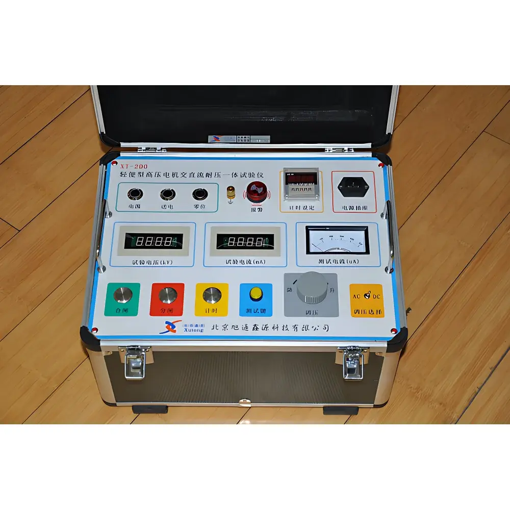
Xutongyongfu XT200-1 Portable AC/DC Motor Dielectric Withstand Tester
| Brand | Xutongyongfu |
|---|---|
| Origin | Beijing, China |
| Manufacturer Type | Authorized Distributor |
| Regional Classification | Domestic (China) |
| Model | XT200-1 |
| Price Range | USD 7,000 – 14,000 (FOB) |
| AC Breakdown Voltage Output | Up to 15 kV (rms) |
| DC Breakdown Voltage Output | Up to 25 kV (dc) |
| Max. Output Current (with reactor compensation) | 550 mA |
| Rated Transformer Capacity | 1.0–1.5 kVA |
| Weight | 22 kg |
| Dimensions (W×D×H) | 400 × 300 × 300 mm |
| Operating Temperature | −15 °C to +50 °C |
| Relative Humidity | ≤90% at +25 °C |
| Compliance | GB 50150–2006, DL/T 596–2005, DL/T 848.2–2004 |
Overview
The Xutongyongfu XT200-1 Portable AC/DC Motor Dielectric Withstand Tester is an integrated high-voltage test system engineered for field and workshop verification of insulation integrity in medium- and high-voltage rotating machines—primarily induction and synchronous motors rated up to 10 kV. Unlike conventional setups requiring separate AC test transformers and DC high-voltage generators, the XT200-1 employs a unified solid-state voltage generation architecture with dual-mode (AC/DC) output capability. It operates on standard single-phase 220 V ±10%, 50 Hz input power and delivers calibrated, traceable AC (50 Hz) and polarity-controlled DC test voltages up to 15 kVrms and 25 kVdc, respectively. The instrument applies the principles of dielectric withstand testing per IEC 60060-1 and IEEE Std 4—measuring insulation resistance stability and detecting localized weaknesses via controlled voltage ramping, dwell, and breakdown detection under defined current-limiting conditions.
Key Features
- Integrated AC/DC high-voltage generation in a single 22 kg chassis—eliminates need for auxiliary HV transformers or DC stacks
- Manually operated zero-position interlocked voltage regulation with analog pointer display for real-time voltage monitoring
- Onboard overcurrent protection (trip threshold: 6.7 A), timed shutdown (0–999 s adjustable, ±0.5% accuracy), and automatic arc-quenching circuitry
- Modular compensating reactor with multiple taps—each labeled with nominal reactive current compensation value (e.g., 100 mA, 200 mA, 350 mA)—enabling stable testing across motor capacitances from 0.05 µF to >2.5 µF
- Low-loss magnetic core design using high-permeability alloy laminations and vacuum-impregnated insulation systems—ensuring thermal stability, minimal audible noise (<45 dB), and humidity resistance (IP2X-rated enclosure)
- Compliance-ready construction: meets mechanical, electrical, and safety requirements of GB 50150–2006 (Acceptance Testing of Electrical Installations), DL/T 596–2005 (Preventive Testing of Power Equipment), and DL/T 848.2–2004 (General Technical Conditions for Power Frequency HV Test Sets)
Sample Compatibility & Compliance
The XT200-1 is validated for use with stator windings of high-voltage AC motors (6 kV and 10 kV classes), including form-wound and random-wound configurations. Its variable-current capability—up to 550 mA when paired with the optional multi-tap reactor—supports testing of motors with wide-ranging capacitance values without external resonance tuning. All voltage outputs are referenced to earth ground and conform to the waveform fidelity and ripple specifications defined in IEC 61000-4-30 Class A for measurement-grade AC; DC output maintains <3% ripple under full load. Calibration certificates are supplied with NIST-traceable references for both AC and DC modes. The unit satisfies electromagnetic compatibility (EMC) requirements per GB/T 17626 series and carries CE-marked safety documentation for export use.
Software & Data Management
The XT200-1 operates in fully manual mode with no embedded microprocessor or digital interface. As such, it does not incorporate data logging, USB connectivity, or PC-based control software. All test parameters—including applied voltage, duration, and pass/fail indication—are recorded manually by the operator using standardized test report forms aligned with ISO/IEC 17025 documentation templates. For laboratories operating under GLP or GMP frameworks, handwritten records must include operator ID, equipment ID (XT200-1 serial number), calibration due date, ambient conditions, and signature. Optional third-party analog-to-digital converters (e.g., National Instruments USB-4431) may be interfaced externally for voltage waveform capture, though this requires independent validation per FDA 21 CFR Part 11 Annex 11 if used in regulated environments.
Applications
- Commissioning tests on newly installed high-voltage motors prior to energization (per GB 50150–2006 Clause 8.0.1)
- Periodic preventive maintenance checks per DL/T 596–2005 Section 11.3 (stator winding AC/DC withstand tests)
- Factory acceptance testing (FAT) of motor rewind services where insulation system requalification is required
- Field diagnostics of suspected insulation degradation following moisture ingress, thermal cycling, or partial discharge events
- Verification of grounding continuity and shield integrity in wound-rotor motor systems during overhaul
FAQ
Does the XT200-1 support automated test sequencing or programmable voltage ramps?
No. It is a manually operated instrument with analog voltage control and fixed timing—designed for simplicity, robustness, and regulatory transparency in field environments.
Can the XT200-1 be used for cable or transformer testing?
It is specifically optimized for rotating machine windings. While limited application to short-length HV cables (<100 m, <1 µF) is possible with reactor compensation, it is not certified for transformer bushing or oil-immersed equipment testing per IEC 60270.
What calibration interval is recommended?
Annual calibration against accredited HV standards is advised; certificate includes verification of AC/DC voltage accuracy (±1.5%), timer deviation (±0.5%), and overcurrent trip threshold.
Is the compensation reactor included with all XT200-1 configurations?
Yes—the multi-tap reactor is standard equipment for all XT200-1 deliveries, regardless of nominal voltage rating (6 kV or 10 kV configuration).
How is safety interlocking implemented during operation?
Mechanical zero-position lock prevents voltage initiation unless the variac is at minimum; front-panel grounding terminals must be connected before enabling output; internal current sensing triggers immediate shutdown if sustained current exceeds 6.7 A for >100 ms.


