MOTIS SCF UL790 Roof Covering Combustibility Test System
| Brand | MOTIS |
|---|---|
| Origin | Jiangsu, China |
| Model | SCF |
| Standards Compliance | ASTM E108, UL 790, NFPA 256, IEC 61730-2 Annex A |
| Test Chamber Dimensions (L×W×H) | 1020 × 1000 × 1473 mm |
| Sample Support Base | 1300 × 1000 × 120 mm Plywood Deck |
| Stainless Steel Fan Duct | 2130 × 762 × 3000 mm |
| Airflow Velocity | 5.5 ± 2.2 m/s (19 ± 8 km/h) |
| Gas Burner Length | 1.12 m, Slot Width: 12.7 mm, Slot Length: 0.91 m |
| Heat Release Rate | Class A/B: 369–387 kWh (21,000–22,000 Btu/min) for 10 min |
| Class C | 316–334 kWh (18,000–19,000 Btu/min) for 4 min |
| Burner Surface Temperature | 880 ± 10 °C |
| Data Acquisition | NI PXI-based LabVIEW system with 16-bit thermocouple input, 16-bit and 12-bit analog I/O modules, real-time & Ethernet communication support |
| Power Supply | 220 V, 50 Hz, 3-phase |
| Minimum Airflow Capacity | 300 m³/min |
| Auto-Ignition Voltage | ≥1.8 kVp |
Overview
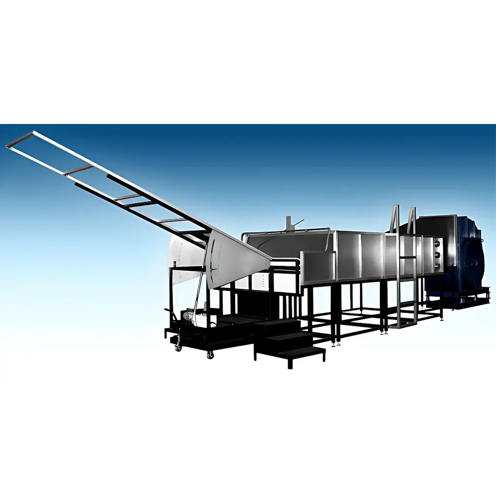
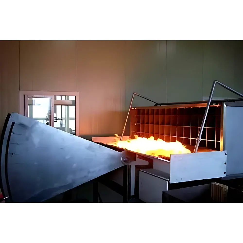
The MOTIS SCF UL790 Roof Covering Combustibility Test System is a rigorously engineered fire performance evaluation platform designed to replicate standardized external flame exposure conditions for roof assemblies and photovoltaic (PV) module mounting systems. It operates in strict accordance with the test protocols defined in UL 790 (Standard for Tests of Fire-Resistant Roof Coverings), ASTM E108 (Standard Test Methods for Fire Tests of Roof Coverings), NFPA 256 (Standard Method of Test for Fire Resistance of Roof Coverings), and IEC 61730-2 Annex A (Fire Propagation Test for PV Modules). The system employs a controlled gas-fired linear burner assembly to deliver calibrated thermal flux across defined exposure durations—10 minutes for Class A and B ratings and 4 minutes for Class C—enabling classification of roof coverings into one of three fire resistance categories based on flame spread, ember generation, and penetration resistance.
Key Features
- Structural steel main frame (1020 × 1000 × 1473 mm) with corrosion-resistant finish, providing mechanical stability during high-temperature operation and repeated thermal cycling.
- Dedicated plywood substrate deck (1300 × 1000 × 120 mm) for secure mounting of full-size roof covering specimens, replicating real-world installation geometry and substrate interaction.
- Non-combustible termination board installed at the distal end of the test deck to suppress under-deck flame re-ignition and ensure compliance with UL 790 boundary condition requirements.
- Adjustable stainless-steel sector plate (1440 × 940 mm) enabling precise angular alignment of specimen orientation relative to incident flame vector, critical for reproducible radiant and convective heat transfer profiles.
- Front-mounted non-combustible fascia assembly (330 × 2130 × 584 mm) simulating eave and rake geometry to direct flame propagation from burner to specimen surface in accordance with standard-defined flame impingement geometry.
- Integrated airflow conditioning system featuring stainless-steel ductwork (2130 × 762 × 3000 mm), honeycomb flow straighteners, and motorized turbulence plates to maintain uniform 5.5 ± 2.2 m/s cross-flow velocity across the test zone—verified via calibrated anemometry.
- High-capacity centrifugal fan (300 m³/min minimum, 220 V / 50 Hz / 3-phase) with infinitely variable reverse-drive controller for dynamic airflow modulation without mechanical backlash or hysteresis.
- Linear gas burner (1.12 m length, 60.3 mm OD) equipped with a 12.7 mm × 910 mm longitudinal slot, delivering repeatable heat release rates of 369–387 kWh (Class A/B) or 316–334 kWh (Class C), with surface temperature maintained at 880 ± 10 °C via closed-loop mass flow control.
- Automated ignition subsystem utilizing high-voltage spark electrodes (≥1.8 kVp) with fail-safe interlocks, eliminating manual flame initiation and ensuring operator safety and test sequence integrity.
- NI PXI-based data acquisition architecture running LabVIEW Real-Time software, supporting synchronized acquisition from 16-bit thermocouple inputs, analog voltage/current sensors, digital I/O, and Ethernet-connected remote monitoring nodes.
Sample Compatibility & Compliance
The SCF system accommodates standard-sized roof covering specimens—including asphalt shingles, metal panels, tile, membrane systems, and integrated PV roofing assemblies—mounted on representative structural decks per ASTM E108 and UL 790 dimensional and fixturing requirements. Its design ensures full alignment with regulatory testing mandates for building code acceptance in North America (IBC, IRC), Canada (NBC), and international markets requiring UL/ETL certification. All hardware, airflow calibration procedures, and burner output verification methods are traceable to NIST-certified reference standards. The system supports audit-ready documentation workflows compliant with GLP and ISO/IEC 17025 laboratory accreditation requirements, including electronic signature capability, audit trail logging, and version-controlled test method execution.
Software & Data Management
LabVIEW-based control and acquisition software provides deterministic real-time execution of test sequences, including automatic ramping of gas flow rates, timed burner activation/deactivation, airflow regulation, and synchronized thermal data capture. The system records time-stamped thermocouple readings (Type K, 16-bit resolution), analog sensor outputs (e.g., pressure, flow rate), and digital status signals (valve positions, fan speed, ignition state) at user-configurable sampling intervals down to 100 ms. Data files are saved in TDMS format with embedded metadata (test ID, operator, standard referenced, environmental conditions) and exported to CSV or MATLAB-compatible structures. Remote access, multi-user role management, and integration with LIMS environments are supported via TCP/IP and RESTful API endpoints. All software modules comply with FDA 21 CFR Part 11 requirements for electronic records and signatures when deployed in regulated quality assurance settings.
Applications
- Fire classification testing of Class A, B, and C roof coverings per UL 790 and ASTM E108.
- Flame propagation assessment of photovoltaic modules and mounting systems under IEC 61730-2 Annex A.
- Development and validation of fire-retardant coatings and substrate treatments for roofing materials.
- Comparative analysis of edge-of-roof fire spread behavior under wind-driven conditions.
- Support for FM Global Approval, UL Certification, and ICC-ES Evaluation Reports.
- Research into fire dynamics at roof-to-wall intersections and combustible deck interactions.
FAQ
Does the SCF system meet UL’s factory inspection requirements for listed testing laboratories?
Yes—the mechanical configuration, calibration schedule, operator training protocol, and documentation framework align with UL’s Requirements for Laboratories Performing Fire Tests (UL 4600) and are compatible with routine surveillance audits.
Can the system be configured for simultaneous multi-zone thermal monitoring?
Yes—up to 64 thermocouple channels can be added via expansion chassis; all channels are time-synchronized and referenced to a common master clock.
Is third-party calibration certification included with delivery?
A full NIST-traceable calibration certificate for airflow sensors, thermocouples, and mass flow controllers is provided upon commissioning, with annual recalibration services available under service agreement.
What safety interlocks prevent unintended burner activation?
Hardware-level interlocks include door position switches, airflow verification sensors, gas pressure monitors, and flame detection via UV/IR sensors—all wired into a SIL-2-rated safety PLC that cuts fuel supply and de-energizes ignition within 50 ms of fault detection.
How is wind profile uniformity validated across the test chamber?
Pre-test grid mapping per ASTM D7504 is performed using a traversing hot-wire anemometer; deviation from target velocity must remain within ±10% across all 25 measurement points before test initiation.


