

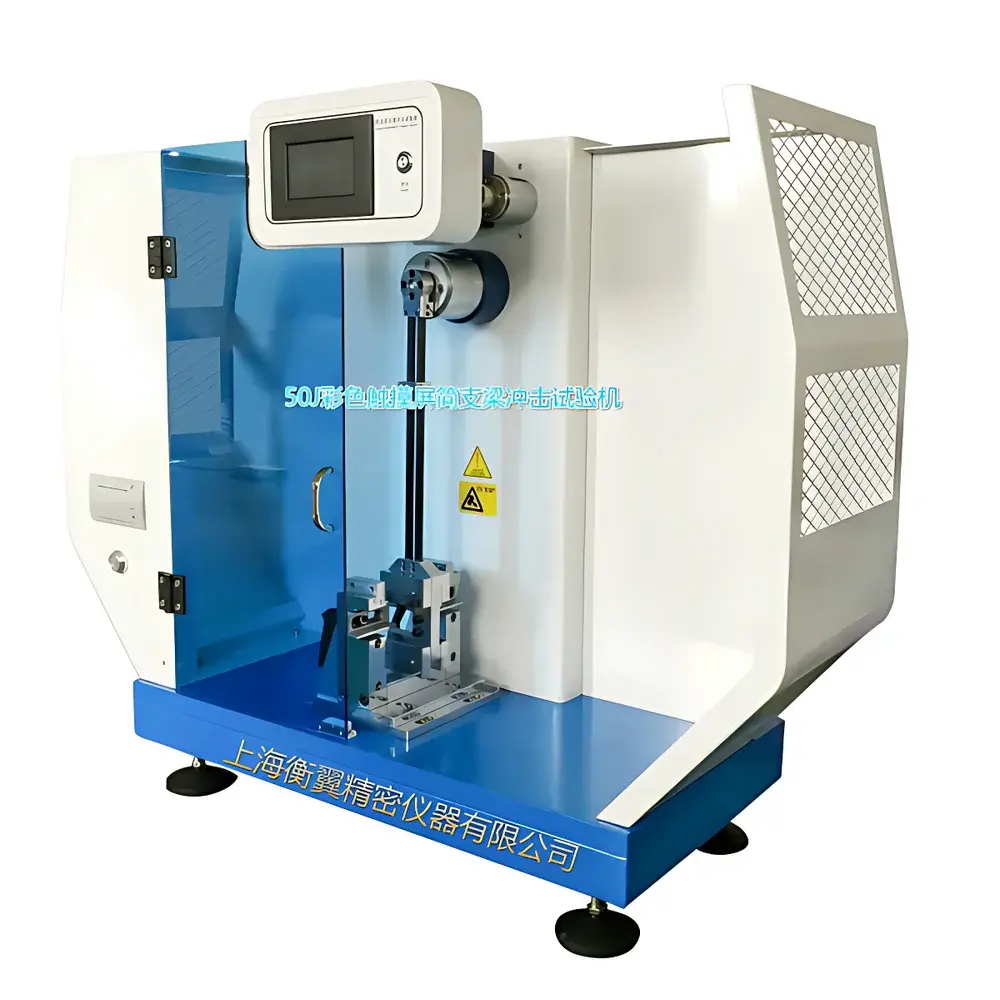
Hengyi HY(JZ)50JTR Charpy Impact Tester for Plastics
| Brand | Hengyi |
|---|---|
| Origin | Shanghai, China |
| Manufacturer | Hengyi Test Equipment Co., Ltd. |
| Model | HY(JZ)50JTR |
| Instrument Type | Pendulum Impact Tester |
| Nominal Impact Energy | 50 J |
| Impact Velocity | 3.8 m/s |
| Pendulum Moment (Impact Constant) | 1 N·m/rad |
| Load Cell Range | 1 kN |
| Maximum Pendulum Lift Height | 395 mm |
| Support Span Options | 40 / 60 / 70 / 95 mm |
| Anvil Radius | R = 1.0 mm |
| Striking Edge Angle | 30° |
| Striking Edge Radius | R = 2.0 ± 0.5 mm |
| Angular Resolution | 0.01° (Omron rotary encoder) |
| Energy Resolution | 0.01 J |
| Display | Color TFT touchscreen (bilingual: EN/CN) |
| Data Storage | 12 test records with auto-averaging |
| Output | Built-in thermal printer |
| Compliance | ISO 179-1:2019, GB/T 1043.1–2023, GB/T 18743–2022, JB/T 8762–2021 |
Overview
The Hengyi HY(JZ)50JTR Charpy Impact Tester is a precision-engineered pendulum impact testing system designed specifically for the determination of Charpy unnotched or notched impact strength of rigid plastics and non-metallic engineering materials—including reinforced nylon, fiberglass-reinforced polymers (GFRP), ceramics, cast stone, and electrically insulating composites. It operates on the fundamental principle of potential-to-kinetic energy conversion: a calibrated pendulum is raised to a defined height, released, and allowed to strike a standardized specimen supported as a simple beam. The residual energy after fracture is measured via high-resolution angular displacement sensing, enabling direct calculation of absorbed impact energy per unit cross-sectional area (J/m or kJ/m²). This method delivers quantitative, reproducible data essential for material qualification, formulation development, quality control, and regulatory conformance in polymer manufacturing and R&D laboratories.
Key Features
- Patented carbon-fiber pendulum arm—optimized for rigidity along the impact axis and mass concentration at the center of percussion—minimizes torsional vibration and ensures true single-plane impact loading, extending service life and improving repeatability.
- High-stability Omron rotary encoder (0.01° angular resolution) coupled with real-time torque compensation algorithms delivers energy measurement accuracy to ±0.01 J across the full 50 J range.
- Aerodynamically profiled striker tip and precision-ground stainless steel anvil mounted on sealed, low-friction ball bearings reduce parasitic energy loss from mechanical hysteresis and air drag.
- Full-color 7-inch capacitive touchscreen interface supports dual-language operation (English/Chinese), intuitive parameter configuration, real-time energy curve visualization, and on-screen calibration verification.
- Integrated microthermal printer outputs traceable test reports including specimen ID, support span, striker geometry, impact energy, energy density units, timestamp, and operator ID—fully compliant with GLP documentation requirements.
- Onboard data management stores up to 12 sequential test results with automatic arithmetic mean calculation, standard deviation, and pass/fail flagging against user-defined thresholds.
Sample Compatibility & Compliance
The HY(JZ)50JTR accommodates standardized rectangular bars (e.g., 80 × 10 × 4 mm per ISO 179-1) and tubular specimens per GB/T 18743–2022. Adjustable support spans (40, 60, 70, and 95 mm) and interchangeable anvils enable strict adherence to specimen geometry requirements across multiple international standards. The system conforms to ISO 179-1:2019 (Plastics — Determination of Charpy impact properties — Part 1: Non-instrumented impact testing), GB/T 1043.1–2023 (identical technical content to ISO 179-1), GB/T 18743–2022 (for thermoplastic piping), and JB/T 8762–2021 (Performance Requirements for Plastic Charpy Impact Testing Machines). All mechanical tolerances—including striking edge radius (R = 2.0 ± 0.5 mm), anvil radius (R = 1.0 mm), and pendulum moment calibration—are verified and certified prior to shipment.
Software & Data Management
No external PC is required for routine operation; all control, acquisition, and reporting are handled by the embedded ARM-based controller running deterministic real-time firmware. Test parameters—including support span, striker type, specimen dimensions, and unit selection (J/m, kJ/m², ft·lb/in, kg·cm/cm)—are configured directly on the touchscreen. Each test record includes raw encoder counts, calculated energy, time stamp, and operator identifier. Data export is supported via USB flash drive in CSV format for integration into LIMS or statistical process control (SPC) platforms. Audit trail functionality logs all calibration events, parameter changes, and firmware updates—meeting foundational requirements for FDA 21 CFR Part 11 compliance when used in regulated environments under documented SOPs.
Applications
- Quality assurance of injection-molded plastic components (e.g., automotive interior trim, electrical housings)
- Comparative evaluation of polymer blends, fillers, and impact modifiers during formulation development
- Batch-to-batch consistency verification for thermoset composites and fiber-reinforced laminates
- Regulatory submission testing for medical device packaging (per ISO 10993-12) and construction-grade PVC profiles
- Educational laboratory instruction on fracture mechanics and polymer viscoelasticity principles
- Third-party certification testing accredited to CNAS (ISO/IEC 17025) and ILAC-MRA scopes
FAQ
What standards does this instrument fully satisfy?
It complies with ISO 179-1:2019, GB/T 1043.1–2023, GB/T 18743–2022, and JB/T 8762–2021 for mechanical, metrological, and safety requirements.
Can the system test notched specimens?
Yes—when equipped with optional notched specimen fixtures and strikers meeting ISO 179-1 Annex A specifications, it supports both unnotched (Type I) and notched (Type II) Charpy tests.
Is calibration traceable to national standards?
Each unit ships with a factory calibration certificate traceable to NIM (National Institute of Metrology, China) via accredited third-party metrology labs.
How is energy loss due to friction compensated?
The system applies dynamic friction correction using pre-characterized bearing torque profiles and air resistance modeling derived from pendulum deceleration curves at multiple initial angles.
Does it support remote monitoring or network connectivity?
Standard configuration includes USB host port for data transfer; Ethernet or RS-232 interfaces are available as optional hardware modules for integration into centralized lab networks.


